Buried anti-floating water tank with bottom plate

A buried, water tank technology, applied in water supply devices, water saving, configuration of water supply pools, etc., can solve the problems of poor anti-floating effect of water tanks, easily polluted water quality, long construction period, etc., and achieve good anti-floating ability. , Excellent anti-floating performance, simple and convenient installation

Pending Publication Date: 2021-12-10
常州瑞尊德智能科技有限公司
View PDF0 Cites 0 Cited by
  • Summary
  • Abstract
  • Description
  • Claims
  • Application Information

AI Technical Summary

Benefits of technology

The present invent describes a new type of buried tanks used in buildings where they are designed to prevent flooding caused by rain falling on them during winter months when snow melting over their top layer due to low temperatures. This design reduces costs while maintaining strong structural integrity without adding extra material like iron bars or other reinforcement. It achieves this through a special way called basement, which helps keep the tank stable even if there's any damage from precipitation. Overall, these technical features improve safety measures against leakages and provide better performance characteristics compared to existing systems.

Problems solved by technology

This technical issue addressed in this patents relates to preventing flooding caused by excessive sedimentation within an underground facility such as a city dwellings where there may have multiple buried water tubs that require maintenance due to their heavy load placed at different levels during installation.

Method used


Image

  • Buried anti-floating water tank with bottom plate
  • Buried anti-floating water tank with bottom plate
  • Buried anti-floating water tank with bottom plate

Examples


Embodiment 1

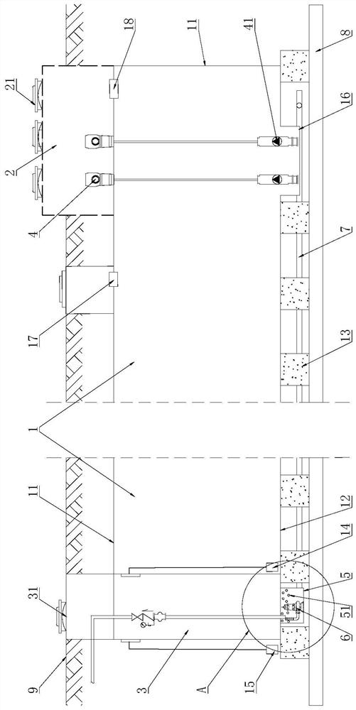
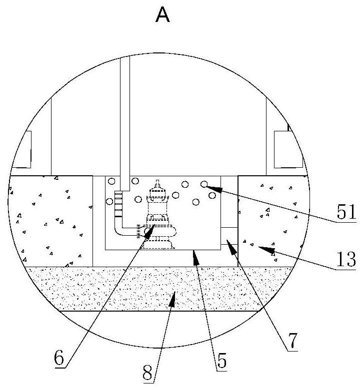
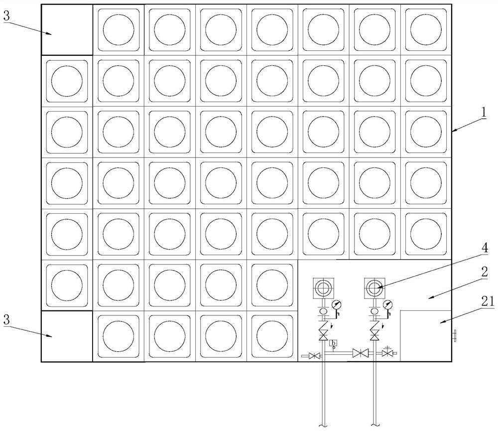
[0029] Such as figure 1 As shown, the buried anti-floating water tank with a floor provided by the present invention includes a water tank 1 , a pump room 2 and a drainage bin 3 . Wherein, the water tank 1 includes a square box body 11 spliced ​​by a plurality of integrally stamped metal molded plates, and a bottom plate 12 connected with the box body 11 . The inside of the box body 11 is provided with multiple groups of criss-cross metal profiles to reinforce the box wall and improve the structural strength of the box body. The inside and the outside of the water tank 1 are respectively equipped with a liquid level monitor 14 in the tank and a liquid level monitor 15 outside the tank. Such as figure 1 As shown, the pump room 2 is arranged at the top of the tank 11, and the pump room 2 is provided with an in-tank pump 4 for pumping the water stored in the water tank 1. The bottom of the water tank 1 is provided with a sump 16 in the tank, the bottom of the sump 16 in the tank

Embodiment 2

[0036] The buried anti-floating water tank with bottom plate provided by this embodiment has the same basic structure as that of Embodiment 1, except that: Figure 5 As shown, the pump room 2 is arranged on the horizontal side of the box body 11, the pump 4 in the water tank is arranged on the bottom floor of the pump room 2, and the floor of the pump room 2 is on the same level as the bottom plate 12 of the water tank 1. The suction pipe of the pump 4 in the water tank runs through the side wall of the casing 11 and the pump head 41 is stretched into the bottom of the sump 16 in the casing, so as to draw the stored water inside the water tank 1 .


PUM


Abstract

The invention relates to the technical field of water tanks, in particular to a buried anti-floating water tank with a bottom plate. The buried anti-floating water tank comprises a water tank, a pump room and a drainage bin, the water tank comprises a tank body and the bottom plate, an in-tank liquid level monitor and an out-tank liquid level monitor are correspondingly mounted inside and outside the water tank, and a water tank inner pump for pumping water stored in the water tank is arranged in the pump room; an out-tank communicating water collecting pit communicating with the drainage bin is arranged below the drainage bin, and an out-tank submersible sewage pump is mounted in the out-tank communicating water collecting pit; and the in-tank liquid level monitor and the out-tank liquid level monitor correspondingly monitor the liquid levels inside and outside the water tank in real time and transmit liquid level data to a background control system in time, the background control system controls the working states of the water tank inner pump and the out-tank submersible sewage pump, so that the water level outside the water tank is not higher than the water level inside the water tank all the time, and therefore, a good anti-floating effect is achieved. The technical problems that a conventional buried water tank is long in construction period, high in manufacturing cost, poor in anti-floating effect, prone to causing water pollution and the like can be solved.

Description


Claims


Application Information

Patent Timeline
Owner 常州瑞尊德智能科技有限公司
Why Eureka
Try Eureka