Three-axis linkage laser welding machine
A laser welding machine and three-axis linkage technology, applied in laser welding equipment, welding equipment, metal processing equipment, etc., can solve the problems of reducing surface reflectivity and laser head damage to the optical system, so as to reduce reflectivity and increase absorption rate Effect
- Summary
- Abstract
- Description
- Claims
- Application Information
AI Technical Summary
Benefits of technology
Problems solved by technology
Method used
Image

Examples
Embodiment 1
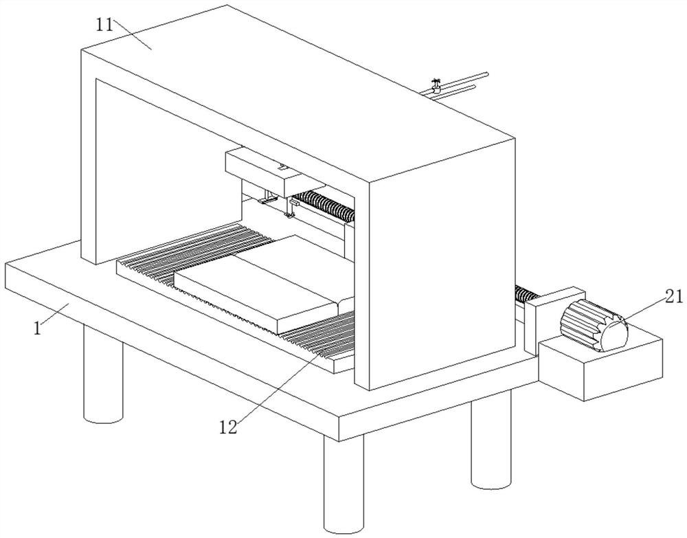
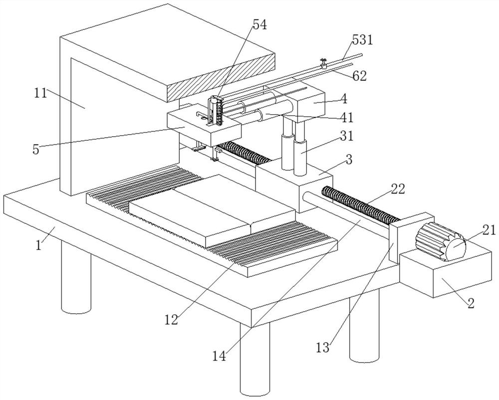
[0024] The invention provides a technical solution: a three-axis linkage laser welding machine, including a workbench 1 and a laser welding head 6, the laser welding head 6 is fixedly connected with a wire 62, and the workbench 1 is provided with a laser welding head 6 for controlling The drive mechanism that moves in the directions of X-axis, Y-axis and Z-axis. The workbench 1 is fixedly connected with a protective frame 11 and a placement table 12 for placing aluminum workpieces. The drive mechanism includes a third mounting block 5, and the laser welding head 6 is fixed. Connected to the third mounting block 5, the third mounting block 5 is provided with an elimination mechanism for eliminating the reflected light generated by the aluminum workpiece when the laser welding head 6 is welding the aluminum workpiece. The elimination mechanism includes a hollow rod 51, which is symmetrical on the hollow rod 51. Rotationally connected with two first straight telescopic rods 52, the t
Embodiment 2
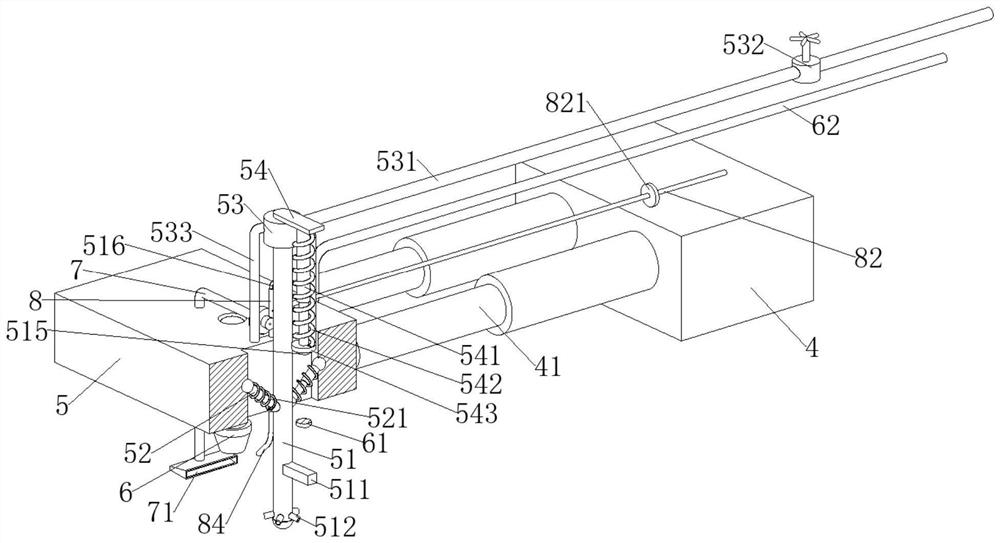
[0033] The elimination mechanism is provided with an absorption mechanism for absorbing metal vapor generated during welding. The absorption mechanism includes a standpipe 8, which is fixedly connected to the third mounting block 5. The bottom of the standpipe 8 is fixedly connected with a nozzle 84. The nozzle 84 Facing the welding position of the laser welding head 6, the vertical pipe 8 is fixedly connected with an inert gas inlet pipe 82, the inert gas inlet pipe 82 is provided with a one-way valve 821, and the hollow rod 51 is fixedly connected with a valve for controlling the vertical pipe 8 and the inert gas. The L-shaped insertion rod 516 connected to the inlet pipe 82 is slidably connected in the vertical pipe 8 .
[0034] refer to image 3 , Figure 5 and Figure 6 , when the hollow rod 51 moves to the highest position relative to the third mounting block 5, the second pressure plate 511 on the hollow rod 51 will touch the second pressure-sensitive switch 61. At this
PUM
 Abstract
Description
Claims
Application Information
 - R&D Engineer
- R&D Manager
- IP Professional
- Industry Leading Data Capabilities
- Powerful AI technology
- Patent DNA Extraction
Browse by: Latest US Patents, China's latest patents, Technical Efficacy Thesaurus, Application Domain, Technology Topic.
© 2024 PatSnap. All rights reserved.Legal|Privacy policy|Modern Slavery Act Transparency Statement|Sitemap