Laser Holing device and two-step holing method

A laser drilling and laser technology, which is applied in the direction of laser welding equipment, electrical components, welding/welding/cutting items, etc., can solve the problems of adverse effects of large-scale industrial use, slow drilling speed, good hole quality, etc., to achieve It is beneficial to industrial application, improving quality and high absorption rate

Inactive Publication Date: 2003-12-17
UNIV OF SCI & TECH OF CHINA
View PDF1 Cites 0 Cited by
  • Summary
  • Abstract
  • Description
  • Claims
  • Application Information

AI Technical Summary

Problems solved by technology

For workpieces with the same thickness and the same material, use conventional long-wavelength lasers, such as non-Q-switched pulsed Nd:YAG fundamental frequency 1064nm laser drilling, and it takes less than 1 second to perforate. Its perforation speed is fast, but The quality of hole formation is poor; while using short-wavelength laser to drill holes, such as the 266nm laser after Q-switching and 4-fold frequency doubling of the above-mentioned long-wavelength laser, it takes 2 to 3 minutes to perforate. Its perforation speed is slow, but the perforation quality is good.
These defects have adverse effects on large-scale industrial use

Method used


Image

  • Laser Holing device and two-step holing method
  • Laser Holing device and two-step holing method
  • Laser Holing device and two-step holing method

Examples


Example Embodiment

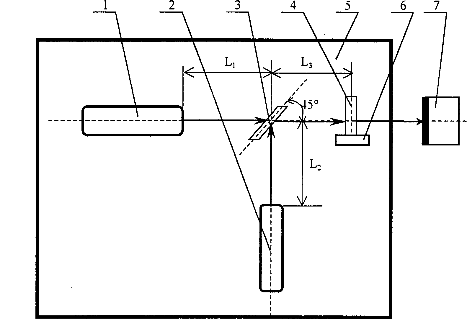
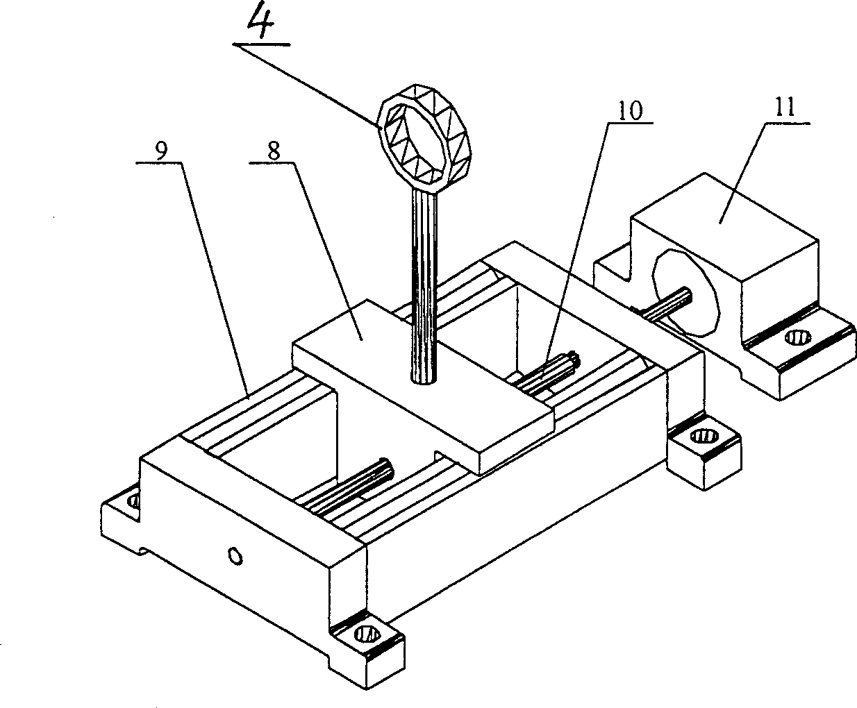
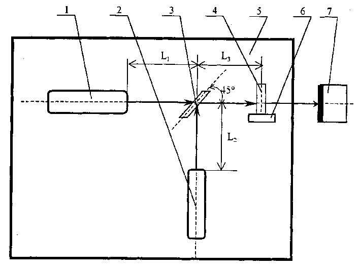
[0012] figure 1 Among them, 1 is the long-wavelength laser S 1 . 2 is short-wavelength laser S 2 . 3 is transmission / reflection plane mirror M 1 , It is able to completely transmit S 1 The output laser can be completely reflected S 2 The transmission / reflection optical plane mirror of the output laser light. 4 is focusing convex lens M 2 . 5 is the bottom plate. S 1 , S 2 , M 1 , M 2 All are installed on this bottom plate. Long Wavelength Laser S 1 With short-wavelength laser S 2 The output laser axis is on the same horizontal plane and perpendicular to each other, the transmission / reflection optical plane mirror M 1 Place the intersection with the axes of the two laser beams, and make an angle of 45° with the two axes respectively, and the two laser beams are located on both sides of the plane mirror respectively. 6 is to place the focusing convex lens M 2 的rail mechanism. 7 is the workpiece to be processed, and the laser axis output by the focusing convex lens is perpendicu


PUM


Abstract

The laser-beam drilling equipment includes a long wavelength laser with long pulse and a short wavelength laser with short pulse, and a transmitting/reflecting plane mirror making an angle of 45 deg.with optical axises of two laser-beams is set at the place where two laser-beams are mutually perpendicular and rendezvous, and a focussing loens capable of moving along the direction of optical circuit is set on the output optical circuit of said mirror. Its hole-drilling process includes two steps; (1) regulating position of focusing lens, starting long wavelength laser to output laser pulse, after the workpiece is drilled, closing the output; (2). regulating the position of focusing lens to make laser focal spot focused on the workpiece surface to be processed equal to the pore size required for process, starting the short-wavelength laser to output laser pulse.

Description


Claims


Application Information

Patent Timeline
Owner UNIV OF SCI & TECH OF CHINA
Why Eureka
Try Eureka