Welding positioning device for capacitor outer shell of electric automobile

An electric vehicle, welding positioning technology, applied in auxiliary devices, welding equipment, auxiliary welding equipment and other directions, can solve the problems of inability to meet production capacity requirements, low welding efficiency, etc., to improve welding efficiency and welding accuracy, and has a simple and convenient structure. The effect of welding

Inactive Publication Date: 2022-01-21
安徽长容电子有限公司
View PDF0 Cites 0 Cited by
  • Summary
  • Abstract
  • Description
  • Claims
  • Application Information

AI Technical Summary

Problems solved by technology

The existing automobile capacitor shell is generally welded on the bottom plate of the flat plate with a bent C-shaped section shell, and the leakage on both sides of the bottom plate forms a flange for fixing. During the welding process of t

Method used


Image

  • Welding positioning device for capacitor outer shell of electric automobile
  • Welding positioning device for capacitor outer shell of electric automobile
  • Welding positioning device for capacitor outer shell of electric automobile

Examples


Embodiment Construction

[0029] It should be understood that the specific embodiments described here are only used to explain the present invention, not to limit the present invention.

[0030] The technical solutions in the embodiments of the present invention will be clearly and completely described below in conjunction with the accompanying drawings in the embodiments of the present invention. Obviously, the described embodiments are only part of the embodiments of the present invention, not all implementations example. Based on the embodiments of the present invention, all other embodiments obtained by persons of ordinary skill in the art without creative efforts fall within the protection scope of the present invention.

[0031]It should be noted that all directional indications (such as up-down-left-right-front-back...) in the embodiments of the present invention are only used to explain the relationship between the components in a certain posture (as shown in the accompanying drawings). If the sp


PUM


Abstract

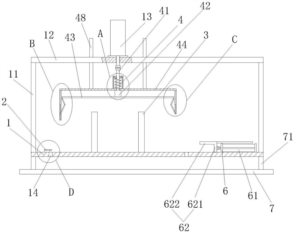
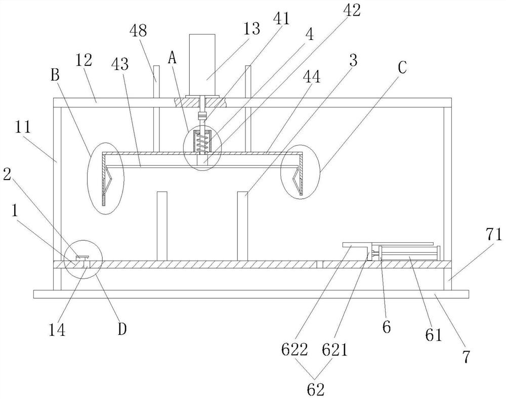
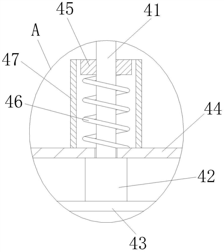
The invention discloses a welding positioning device for a capacitor outer shell of an electric automobile. The welding positioning device comprises a mounting plate, the mounting plate is fixedly connected with a first check block used for limiting a welding workpiece bottom plate, the mounting plate is fixedly connected with a limiting column, and the limiting column is used for limiting the rear side of a workpiece; supporting rods are fixedly connected to the two sides of the mounting plate, a supporting plate is fixedly connected to the supporting rods, a first linear driving device is fixedly mounted on the supporting plate, a first linear driving shaft which drives up and down is arranged at the lower end of the first linear driving device, and the first linear driving shaft penetrates through the supporting plate and is connected with a first guide clamping mechanism; and the first guide clamping mechanism is used for clamping a to-be-welded outer shell at a relative position on the bottom plate. According to the welding positioning device, the workpiece can be conveniently guided, positioned and clamped, so that the workpiece can be conveniently welded, and the welding efficiency and the welding precision are improved; and the structure is simple, and welding slag can be prevented from affecting positioning accuracy.

Description


Claims


Application Information

Patent Timeline
Owner 安徽长容电子有限公司
Why Eureka
Try Eureka