Rapid vacuum circuit breaker and control system thereof

A vacuum circuit breaker and main circuit breaker technology, which is applied to high-voltage air circuit breakers, circuits, electrical components, etc., can solve the problems of power system stability and power transmission capacity that cannot meet the needs of 500kV transmission lines

Pending Publication Date: 2022-02-25
GUANGZHOU POWER SUPPLY BUREAU GUANGDONG POWER GRID CO LTD
View PDF7 Cites 0 Cited by
  • Summary
  • Abstract
  • Description
  • Claims
  • Application Information

AI Technical Summary

Benefits of technology

This patented technology allows for quick breaking down high voltage circuits quickly without causing damage or affecting other components on their way back upstream. It achieves this by connecting multiple units together through an assembly called a combination unit module (CU). Each CSU contains different types of electrical devices like transistor relays and inductors. These elements are then combined into one larger structure called a single fractured plane. By reducing the length of these connections between them, they become more stable over longer periods of use compared to traditional methods such as wire tapping.

Problems solved by technology

The technical problem addressed in this patents relating to power systems involves ensuring reliable transfer between generators at different points along their own distribution network without experiencing any issues such as insufficient stabilization limits caused by overheated wires. This requires developing circuits with shorter interrupt times while still allowing them to continue function properly even if they become disconnected due to external disturbances like lightning strikes.

Method used


Image

  • Rapid vacuum circuit breaker and control system thereof
  • Rapid vacuum circuit breaker and control system thereof
  • Rapid vacuum circuit breaker and control system thereof

Examples


Embodiment 1

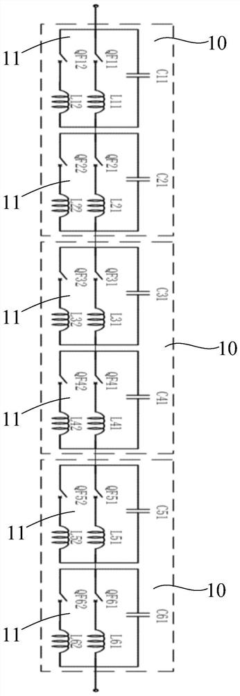
[0033] figure 1 It is a schematic diagram of the principle of the rapid vacuum circuit breaker described in the embodiment of the present invention.

[0034]The embodiment of the present invention provides a fast vacuum circuit breaker, which is applied to a 500KV transmission line. The fast vacuum circuit breaker includes at least three unit modules 10 connected in series, and each unit module 10 includes two groups of circuit breaker assemblies connected in series 11. Each circuit breaker assembly 11 includes at least a first main circuit breaker, a second main circuit breaker and a voltage equalizing capacitor connected in parallel, and the first main circuit breaker is also connected in series with the first current sharing reactance and then connected in parallel with the voltage equalizing capacitor, The second main circuit breaker is also connected in series with the second current sharing reactance and then connected in parallel with the voltage sharing capacitor.

[003

Embodiment 2

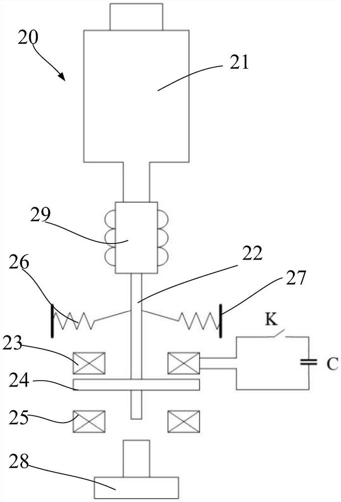
[0062] Figure 4 It is a frame diagram of the control system of the fast vacuum circuit breaker described in the embodiment of the present invention.

[0063] Such as figure 2 and Figure 4 As shown, the embodiment of the present invention also provides a control system for a fast vacuum circuit breaker, which is applied to a 500KV transmission line, including a control module 30 for controlling the operation of the above-mentioned fast vacuum circuit breaker and a The power supply module 40 of the voltage equalizing capacitor power supply C.

[0064] In the embodiment of the present application, the control module 30 includes an acquisition command sub-module 31, a discharge sub-module 32 and an execution sub-module 33;

[0065] Obtaining a command sub-module 31, configured to obtain command information for closing or opening the fast vacuum circuit breaker;

[0066] The discharge sub-module 32 is used to control the voltage equalizing capacitor to discharge to the opening


PUM

PropertyMeasurementUnit
Capacitanceaaaaaaaaaa

Abstract

The invention relates to a quick vacuum circuit breaker and a control system thereof, which are applied to a 500KV power transmission line. The quick vacuum circuit breaker comprises at least three unit modules which are connected in series, and each unit module comprises two groups of circuit breaker assemblies which are connected in series; each group of circuit breaker assembly at least comprises a first main circuit breaker, a second main circuit breaker and a voltage-sharing capacitor which are connected in parallel, the first main circuit breaker is further connected with the first current-sharing reactor in series and then connected with the voltage-sharing capacitor in parallel, and the second main circuit breaker is further connected with the second current-sharing reactor in series and then connected with the voltage-sharing capacitor in parallel. According to the quick vacuum circuit breaker, a multi-break serial quick vacuum circuit breaker is formed by a unit module consisting of three serial unit modules and four main circuit breakers which are connected in parallel and in series, and the on-off time of the quick vacuum circuit breaker is reduced to 10ms, and the technical problem that the stability and the power transmission capacity of a 500kV power transmission line power system cannot be met due to the fact that the on-off time of a switch of an existing circuit breaker is 40ms is solved.

Description


Claims


Application Information

Patent Timeline
Owner GUANGZHOU POWER SUPPLY BUREAU GUANGDONG POWER GRID CO LTD
Why Eureka
Try Eureka