Driving circuit, driving device, electronic equipment and kitchen ware sterilizer

A driving circuit and circuit technology, applied in the fields of driving circuits, driving devices, electronic equipment and kitchen sterilizers, can solve the problems that ultraviolet germicidal lamps cannot maintain constant current and affect the sterilization effect, so as to improve the sterilization effect and reduce power consumption. Effect

Pending Publication Date: 2022-04-05
GREE ELECTRIC APPLIANCES INC OF ZHUHAI
View PDF0 Cites 0 Cited by
  • Summary
  • Abstract
  • Description
  • Claims
  • Application Information

AI Technical Summary

Problems solved by technology

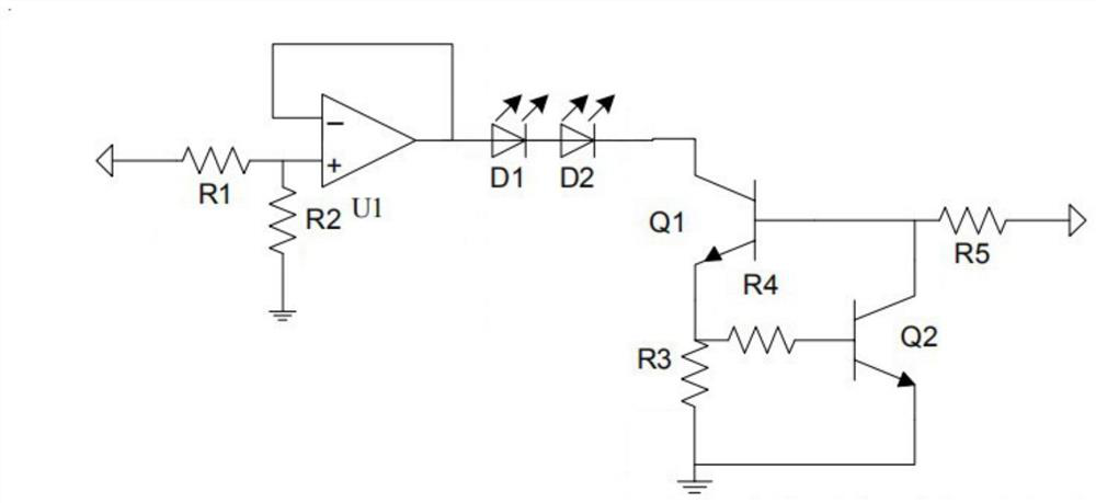
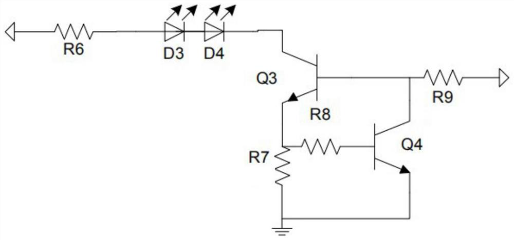
[0003] In order to solve the technical problem of affecting the sterilization effect caused by the inability of the ultraviolet germicidal lamp to maintain a constant current in the prior art, the present invention provides a driving circuit, including: a first constant voltage circuit, a sterilization circuit and a first constant current circuit,

Method used


Image

  • Driving circuit, driving device, electronic equipment and kitchen ware sterilizer
  • Driving circuit, driving device, electronic equipment and kitchen ware sterilizer
  • Driving circuit, driving device, electronic equipment and kitchen ware sterilizer

Examples


Example Embodiment

[0042] In order to make the purpose, technical solution and advantages of the present invention clearer, the present invention will be described in further detail below in conjunction with the accompanying drawings, and the described embodiments should not be considered as limiting the present invention, and those of ordinary skill in the art do not make any All other embodiments obtained under the premise of creative labor belong to the protection scope of the present invention.

[0043] In the following description, references to "some embodiments" describe a subset of all possible embodiments, but it is understood that "some embodiments" may be the same subset or a different subset of all possible embodiments, and Can be combined with each other without conflict.

[0044] If there is a similar description of "first / second / third" in the application documents, add the following explanation. In the following description, the term "first / second / third" is only to distinguis


PUM


Abstract

The invention discloses a driving circuit, which comprises a first constant voltage circuit, a sterilization circuit and a first constant current circuit, and is characterized in that the input end of the first constant voltage circuit is connected with a power supply, the output end of the first constant voltage circuit is connected with the input end of the sterilization circuit, and the first constant voltage circuit is used for outputting a constant voltage; the output end of the sterilization circuit is connected with the first input end of the first constant current circuit, and the sterilization circuit is used for emitting ultraviolet rays with preset wavelengths; the second input end of the first constant-current circuit is connected with the power supply, the output end of the first constant-current circuit is grounded, and the first constant-current circuit is used for keeping the current of the sterilization circuit constant.

Description


Claims


Application Information

Patent Timeline
Owner GREE ELECTRIC APPLIANCES INC OF ZHUHAI
Why Eureka
Try Eureka