Method for regulating and controlling activity of catalyst by utilizing continuous flow photocatalytic reaction device and application of method

A photocatalytic reactor, a technology for catalytic reaction, applied in physical/chemical process catalysts, metal/metal oxide/metal hydroxide catalysts, chemical instruments and methods, etc. Difficulty in recycling photocatalysts, small loading of fixed photocatalysts, etc., to achieve the effects of flexible control and precise utilization, prolonging hydraulic retention time, and flexibly adjusting the intensity and position of light sources

Pending Publication Date: 2022-06-07
GUANGDONG UNIV OF TECH
View PDF8 Cites 1 Cited by
  • Summary
  • Abstract
  • Description
  • Claims
  • Application Information

AI Technical Summary

Benefits of technology

This patented technology describes an apparatus used to treat contaminated fluids such as industrial discharges containing harmful substances like uranium dioxide (UO2). By allowing certain chemical agents called activators to react with specific compounds found within these materials, they are able to remove unwanted material without affecting their effectiveness. These techniques allow for effective remedial action quickly and efficiently over large areas. Additionally, there may also include various methods to change the concentration level of active ingredients inside the solution before being exposed to sunlight. Overall, this technology allows for better monitoring and management of environmental concerns caused by disposal of hazardous products.

Problems solved by technology

This patents discusses different methods used for treating contaminated waters such as sewage or wastewater. These techniques include chemical oxides (CLO), photoelectric conversion, electrocatalysers, biological agents like bacteria, algae, yeast cells, etc., but they all require some form of external power supply to work properly. To address these issues, there exist various types of devices called reactors - fixed bed systems where several lights act together to improve their performance over time without being limitedly controlled individually.

Method used


Image

  • Method for regulating and controlling activity of catalyst by utilizing continuous flow photocatalytic reaction device and application of method
  • Method for regulating and controlling activity of catalyst by utilizing continuous flow photocatalytic reaction device and application of method
  • Method for regulating and controlling activity of catalyst by utilizing continuous flow photocatalytic reaction device and application of method

Examples


Embodiment 1

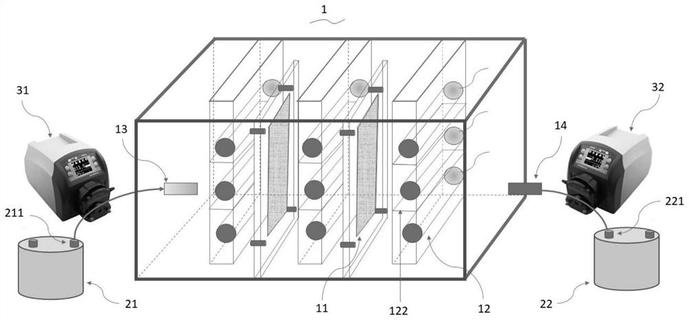
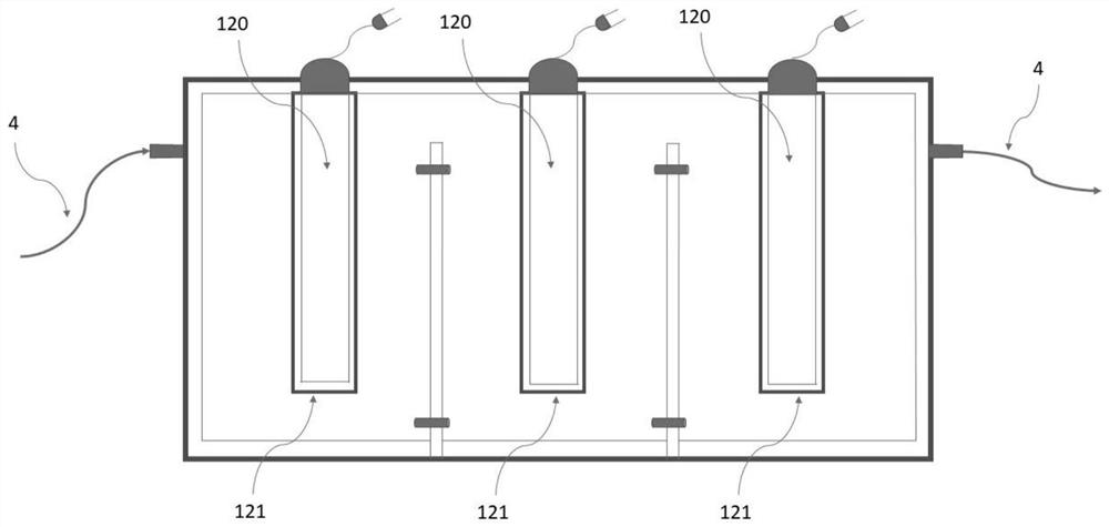
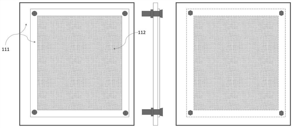
[0032] figure 1 It is a structural diagram of the high-efficiency and energy-saving continuous flow photocatalytic reaction device of the present invention. figure 2 It is a top view of the photocatalytic reaction device of the present invention. like figure 1 and figure 2 As shown, an efficient and energy-saving continuous flow photocatalytic reaction device comprises a photocatalytic reactor 1, a liquid storage tank 2 and a single-channel peristaltic pump 3; the liquid storage tank 2 is connected with the photocatalytic reactor 1 through a silica gel tube 4 , the single-channel peristaltic pump is arranged on the silicone tube to control the flow of the fluid to be treated at the inlet and outlet of the reactor; the photocatalytic reactor 1 is provided with a photocatalyst assembly 11 and an ultraviolet lamp group 12 inside; The photocatalyst assembly 11 and the ultraviolet lamp group 12 are cross-fixed on different sides of the photocatalytic reactor 1, and the distance f


PUM

PropertyMeasurementUnit
Sizeaaaaaaaaaa

Abstract

The invention belongs to the technical field of photocatalytic oxidation, and discloses a method for regulating and controlling the activity of a catalyst by utilizing a continuous flow photocatalytic reaction device and application of the method. The method comprises the following steps: putting a diluent of a target pollutant into a liquid storage tank, and tightly connecting the liquid storage tank with a photocatalytic reactor through a silicone tube; according to the method, a single-channel peristaltic pump is used for controlling the water inlet flow rate to be 5-30 mL/min and the water outlet flow rate to be 1-15 mL/min respectively, it is guaranteed that the average water flow speed is 3-20 mL/min, the device operates in a continuous flow state, and a catalyst is continuously excited by ultraviolet light till target pollutants are completely oxidized. According to the method, the contact time of a target object and a catalyst is changed by adjusting the flow speed of a to-be-treated fluid at a water inlet and a water outlet under the condition that the target object is efficiently treated, so that the activity and the service life of the catalyst are regulated. The method can be used for research of related mechanisms such as catalyst deactivation and the like, and the fields of medical wastewater treatment, sewage treatment secondary effluent or deep purification of urban drinking water and the like.

Description


Claims


Application Information

Patent Timeline
Owner GUANGDONG UNIV OF TECH
Why Eureka
Try Eureka