Wire drawing equipment for Internet of Things engineering

A technology of the Internet of Things and engineering, applied in the direction of thin material processing, delivery of filamentous materials, transportation and packaging, etc., can solve the problems of inconvenient pulling wires, reducing equipment finishing, lack of easy-to-adjust angle mechanisms, etc., to improve finishing, The effect of improving the convenience of adjustment

Inactive Publication Date: 2022-07-01
天津华融金服科技有限公司
View PDF0 Cites 0 Cited by
  • Summary
  • Abstract
  • Description
  • Claims
  • Application Information

AI Technical Summary

Benefits of technology

The technical effect described by this patented technology allows for easier control over devices during manufacturing processes while also allowing them to rotate or move along with their wires without being affected by any obstacles such as other components around it. This makes assembly more efficient and reliable compared to traditional methods like threading and bending.

Problems solved by technology

This patented technical problem addressed during the development phase of internetof things (IoT) projects involves improving the efficiency with which wires are pulled out without being bent excessively or causing damage when they fall off. Current methods require manual labor that may make them difficult to manage and reduce their effectiveness over time. Additionally, there can be issues where the wiring cannot follow certain directions accurately because no suitable angles have been provided.

Method used


Image

  • Wire drawing equipment for Internet of Things engineering
  • Wire drawing equipment for Internet of Things engineering

Examples


Embodiment Construction

[0017] In order to make the technical means, creative features, achievement goals and effects realized by the present invention easy to understand, the present invention will be further described below with reference to the specific embodiments.

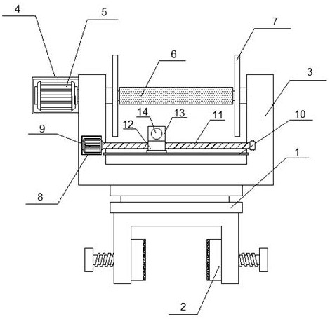
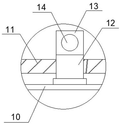
[0018] like Figure 1-2 As shown, a wire-pulling device for Internet of Things engineering includes a rotary damper 1, the top of the rotary damper 1 is provided with a concave support frame 3, and the top of one side of the concave support frame 3 is provided with a protective box A4, so The inner screw of the protective box A4 is provided with a motor A5, and the inner top of the concave support frame 3 is connected with a wire pulling roller 6 through a rotating shaft. One side of the surface is provided with a protective box B8, the screws of the protective box B8 are provided with a motor B9, the bottom of the protective box B8 is provided with a slide rail 10 through a bracket, and one side of the protective box B8 is located on t


PUM


Abstract

The invention discloses wire drawing equipment for Internet of Things engineering, which comprises a rotary damper, a concave support frame is arranged at the top of the rotary damper, a protection box A is arranged at the top of one side of the concave support frame, a motor A is arranged in the protection box A through a screw, and a wire drawing roller is connected to the top of the inner side of the concave support frame through a rotary shaft. Limiting discs are arranged at the two ends of the wire drawing roller in a penetrating mode, a protection box B is arranged on one side of the surface of the concave supporting frame and provided with a motor B through screws, a sliding rail is arranged at the bottom of one side of the protection box B through a support, a reciprocating lead screw is arranged at the position, located on the top of the sliding rail, of one side of the protection box B, and the surface of the reciprocating lead screw is sleeved with a sliding sleeve. And a limiting block is arranged at the top of the sliding sleeve. The wire drawing device is provided with a uniform wire drawing structure, so that wire bodies can be tidied while wire drawing is carried out, and the wire drawing device is suitable for being widely popularized and used.

Description


Claims


Application Information

Patent Timeline
Owner 天津华融金服科技有限公司
Why Eureka
Try Eureka