Scanner for medical optical imaging device employing suppression of optical reflections

An optical imaging and scanner technology, applied to radiological diagnostic instruments, measuring devices, scientific instruments, etc., can solve problems such as inability to use reappearance images, formation of artifacts, etc.

Inactive Publication Date: 2003-07-09
IMAGING DIAGNOSTIC SYST
View PDF5 Cites 4 Cited by
  • Summary
  • Abstract
  • Description
  • Claims
  • Application Information

AI Technical Summary

Problems solved by technology

Reflected light inside the scanner can also creat

Method used


Image

  • Scanner for medical optical imaging device employing suppression of optical reflections
  • Scanner for medical optical imaging device employing suppression of optical reflections
  • Scanner for medical optical imaging device employing suppression of optical reflections

Examples


Embodiment Construction

[0026] US5692511, US6100520 and US6130958 all disclose a medical optical imaging device, which are hereby incorporated by reference.

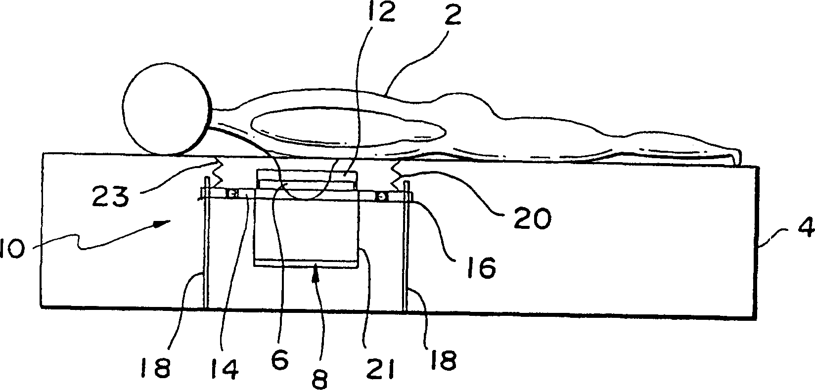
[0027] Such as figure 1 As shown, the patient 2 is lying face down on the scanning table 4 , with the breast 6 hanging in the scanning cavity 8 . The medical optical imaging device 10 includes a collimator 12 fixed on an orbiting plate 14 and a lifting plate 16 . Collimator 12 links with detector 13 (see Figure 5 ). The orbiting plate 14 is rotated in a circle around the breast to obtain a portion of the data. The drive screw 18 moves the lift plate 16 vertically to position the orbiting plate 14 at different vertical positions and rotates in a circle around the breast in this position to obtain another portion of the data. The side barrier 20 is fixed on the lower side of the scanning table 4 and the lifting plate 16, thereby providing an external light for the scanning cavity 8 composed of the side barrier 20, the orbiting plate 14, the lif


PUM


Abstract

A scanner (10) for a medical optical imaging device, comprises an illumination source positioned to direct emitted light (40) into a breast (6) positioned below a support surface; a plurality of detectors (13) positioned to detect light emerging from the breast; and a container (21) disposed below the illumination source and the detectors (13) adapted to trap light reflected from the breast.

Description


Claims


Application Information

Patent Timeline
Owner IMAGING DIAGNOSTIC SYST
Why Eureka
Try Eureka