Steel plate externally-rived stengthening method for reinforced concrete structure and its special-purpose rivet

A reinforced concrete and concrete technology, used in bridge reinforcement, building construction, building maintenance, etc., can solve the problems of difficult quality assurance, uneconomical, poor temperature and weather resistance, and achieve easy quality assurance, low construction cost, and weather resistance. Good results

Inactive Publication Date: 2003-12-10
郑州长建工程技术开发有限公司
View PDF0 Cites 7 Cited by
  • Summary
  • Abstract
  • Description
  • Claims
  • Application Information

AI Technical Summary

Benefits of technology

In this patented technology for strengthening structural members by adding extra layers or adhesive tape between them during installation. By doing things like crimping metal rods onto these added materials, it becomes stronger without requiring more expensive equipment such as punches or bolts. Additionally, there's also good thermal insulation properties when used with certain types of resin cements. Overall, this innovation provides an efficient way to improve durability while reducing costs associated with existing methods.

Problems solved by technology

The present patents discuss different types of techniques called strengthening and restoring concretency modulation technology, including bonding reinforceings between metal elements such as iron sheets and concrete composites. However, these existing processes have limitations related to complexity, environmental impact, time consumption, and economics. There remains an issue where poor thermal/weathing resistances may lead to failure overtime due to cracks formed during service life. Additionally, current methods require expensive equipment like punchers and roller blinds, leading to increased costs compared to traditional methods.

Method used


Image

  • Steel plate externally-rived stengthening method for reinforced concrete structure and its special-purpose rivet
  • Steel plate externally-rived stengthening method for reinforced concrete structure and its special-purpose rivet
  • Steel plate externally-rived stengthening method for reinforced concrete structure and its special-purpose rivet

Examples


specific Embodiment 1

[0085] Specific embodiment 1 is a typical rivet steel reinforcement method 1: using rivet steel reinforcement method to increase the main reinforcement of the beam

[0086] As shown in Figures 8 and 9, the size of the rectangular cross-section lintel is: 120mm (height) × 240mm (width), the span is 2m, the design requires the reinforcement at the bottom of the beam to be 3φ12, and the actual reinforcement is only 2φ6. Now, a 6mm strip is riveted at the bottom Reinforced by 80mm steel slats.

[0087] Steel slat design maximum tensile strength:

[0088] 6mm×(80mm-14mm)×210N / mm 2 =83.16kN, where 14mm is the hole diameter of the steel plate.

[0089] The number of rivets in the 1 / 4 length range at both ends of the steel strip:

[0090] 83.16kN / 20kN=4.15 (pieces), 5 pieces are actually selected, that is, 1 rivet is arranged in a 10cm arrangement, and the design tensile force of each rivet is 20kN.

[0091] The rivets in the middle of the steel strips are arranged according to

Embodiment 2

[0093] Example 2 is a typical reinforcement method 2: using riveted steel reinforcement method to increase the stirrups of the beam

[0094] As shown in Figures 10, 11, and 12, a beam with a rectangular cross-section has a cross-sectional size of 240mm (height) × 120mm (width) and a span of 2m. According to the design requirements, it is necessary to add stirrups within 60cm on both sides of the beam. The amount of added stirrups is 5 φ10 steel bars with a spacing of 150mm to improve the shear resistance of the beam. Now it is reinforced by riveting five 3mm×50mm parallel U-shaped hoop slats at the beam end. The maximum tensile force of the steel slats is:

[0095] 3mm×(50mm-12mm)×210N / mm 2 =23.9kN, where 12mm is the aperture size of the steel plate.

[0096] The number of rivets in the 1 / 4 length range of both ends of the steel plate: 23.9kN / 20kN=1.2 (pieces), actually choose 2, where 20kN is the tensile force of a single rivet.

[0097] The total length of the U-shaped


PUM

PropertyMeasurementUnit
Tensile strengthaaaaaaaaaa

Abstract

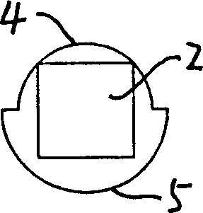
The present invention relates to a method for reinforcing reinforced concrete structure by externally riveting steel plate and its special-purpose rivet. The reinforcing steel plate strip can be riveted on the surface of the concrete member from exterior of the concrete member, and the described rivet is made into the form of that the half of the rivet head of said rivet is semicylindrical form, and another half of semiconical form, and the cross-section of said rivet body is rectangular, and the transition portions between four planes of rivet head and rivet body are made into the oblique surface structure.

Description


Claims


Application Information

Patent Timeline
Owner 郑州长建工程技术开发有限公司
Why Eureka
Try Eureka