Cermic Sizing material fast and controllable solidfying colloied state shaping method and device
A ceramic slurry and molding method technology, which is applied in ceramic molding machines, chemical instruments and methods, cement mixing devices, etc., can solve the problems of long curing time, slurry curing, and uncured, and achieve short curing time and uniform curing , the effect of a high level of automation
- Summary
- Abstract
- Description
- Claims
- Application Information
AI Technical Summary
Problems solved by technology
Method used
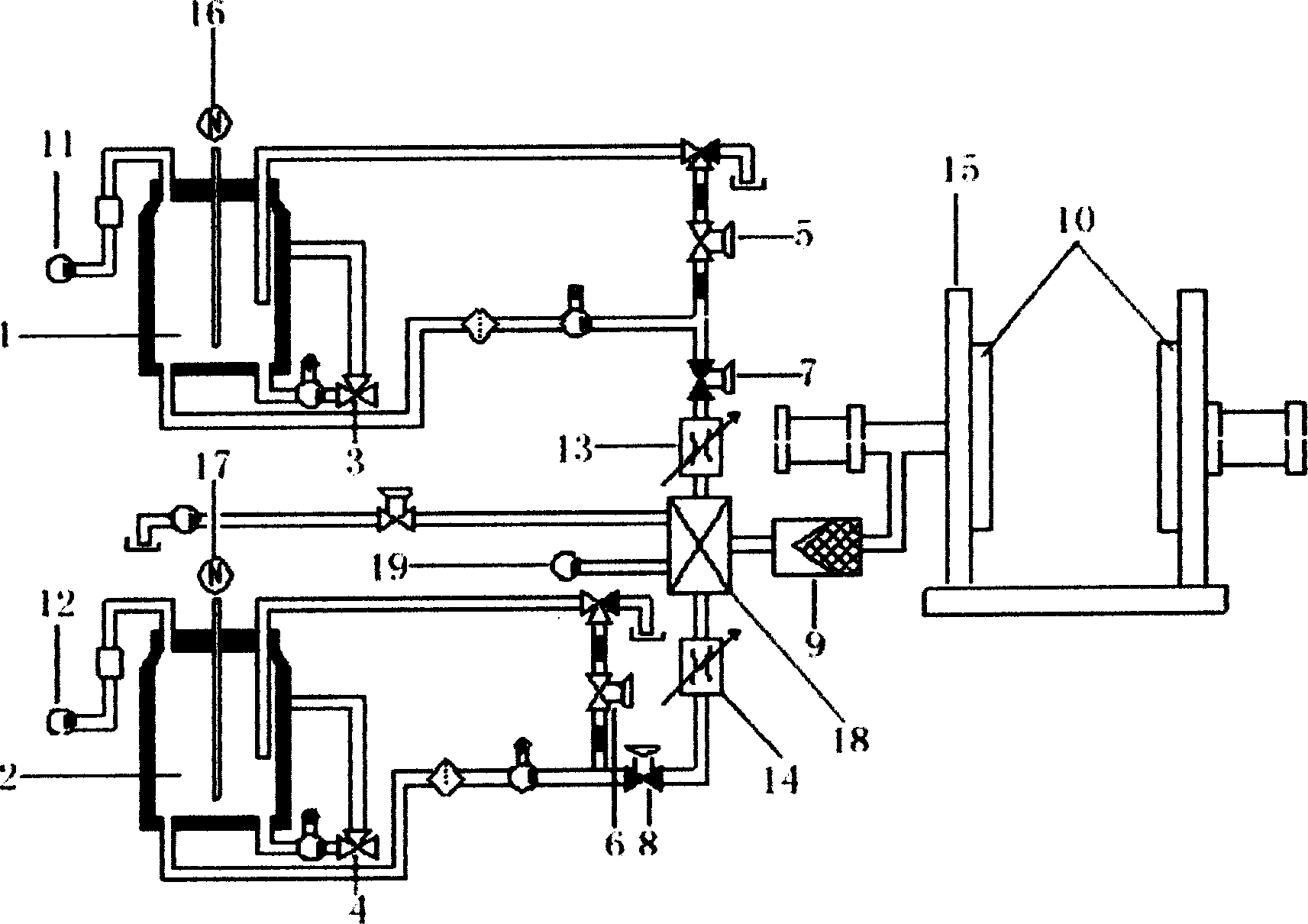
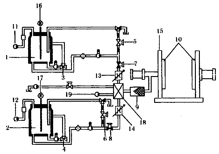
Image

Examples
Example Embodiment
[0040] Example 1 Molding of alumina ceramics
[0041] α-Al 2 O 3 It is a commercially available industrial raw material with a particle diameter of about 2μm and a relatively uniform shape. Adjust the pH value between 3.5 and 4 with hydrochloric acid in deionized water, add 6Kg of alumina ceramic powder, and after ball milling for 24 hours, prepare a suspension with a viscosity of 280mPa·s and a volume fraction of 60%, and place it in material A In the tank, the alumina is now positively charged. Use ammonium citrate as dispersant in deionized water, pH value between 5-6, add alumina ceramic powder 6Kg, after ball milling for 24 hours, prepare a suspension with a viscosity of 200mPa·s and a volume fraction of 60% , Placed in the B material tank, at this time the alumina is negatively charged due to the adsorption of ammonium citrate. The slurry in the two tanks A and B are respectively measured 50ml through a diaphragm metering pump, and injected into the static mixer through an 8MPa
Example Embodiment
[0042] Example 2 Molding of alumina ceramics
[0043] α-Al 2 O 3 It is a commercially available industrial raw material with a particle diameter of about 0.5 μm and a spherical shape. Adjust the pH to between 3.5 and 4 with hydrochloric acid in 1000ml of deionized water, add 6Kg of alumina ceramic powder and 5g of 0.4mmol / l calcium chloride electrolyte, and after ball milling for 24 hours, the viscosity will be 360mPa·s. The suspension with a volume fraction of 60% is placed in the A tank, where the alumina is positively charged. Use 5g of ammonium citrate as a dispersant in 1000ml of deionized water, pH value between 5-6, add alumina ceramic powder 6Kg and 0.4mmol / l ammonium sulfate electrolyte 5g, after ball milling for 24 hours, the viscosity is A suspension of 300 mPa·s and a volume fraction of 60% is placed in the B material tank. At this time, the alumina is negatively charged due to the adsorption of ammonium citrate. The slurry in the two tanks A and B are respectively me
Example Embodiment
[0044] Example 3 Molding of silicon carbide ceramic
[0045] SiC is a commercially available industrial raw material, and the particle diameter is about 0.7 μm. A premix containing 16wt% of acrylamide monomer and methylenebisacrylamide was prepared with deionized water. The ratio of methylene bisacrylamide to acrylamide is 1:12. The powders of group A are prepared by using the premixed liquid to prepare a concentrated suspension of silicon carbide ceramics with a volume fraction of 55 vol%, and a catalyst tetramethylethylenediamine is added at the same time. After ball milling for 24 hours, the viscosity is less than 100 mPa·s. Component B is directly prepared with deionized water with 55vol% volume fraction of silicon carbide ceramic concentrated suspension, while adding initiator ammonium persulfate or hydrogen peroxide 5g, after ball milling for 24 hours, the viscosity is less than 150mPa·s. The slurry in the two tanks A and B are respectively measured by a diaphragm metering pump
PUM
| Property | Measurement | Unit |
|---|---|---|
| Diameter | aaaaa | aaaaa |
| Viscosity | aaaaa | aaaaa |
Abstract
Description
Claims
Application Information
 - R&D Engineer
- R&D Manager
- IP Professional
- Industry Leading Data Capabilities
- Powerful AI technology
- Patent DNA Extraction
Browse by: Latest US Patents, China's latest patents, Technical Efficacy Thesaurus, Application Domain, Technology Topic.
© 2024 PatSnap. All rights reserved.Legal|Privacy policy|Modern Slavery Act Transparency Statement|Sitemap