Display panel
A display panel and panel technology, applied in the direction of static indicators, etc., can solve the problems of detecting frame glue coating, frame glue broken line coating, frame glue inspection quality impact, etc.
- Summary
- Abstract
- Description
- Claims
- Application Information
AI Technical Summary
Problems solved by technology
Method used
Image

Examples
no. 1 example
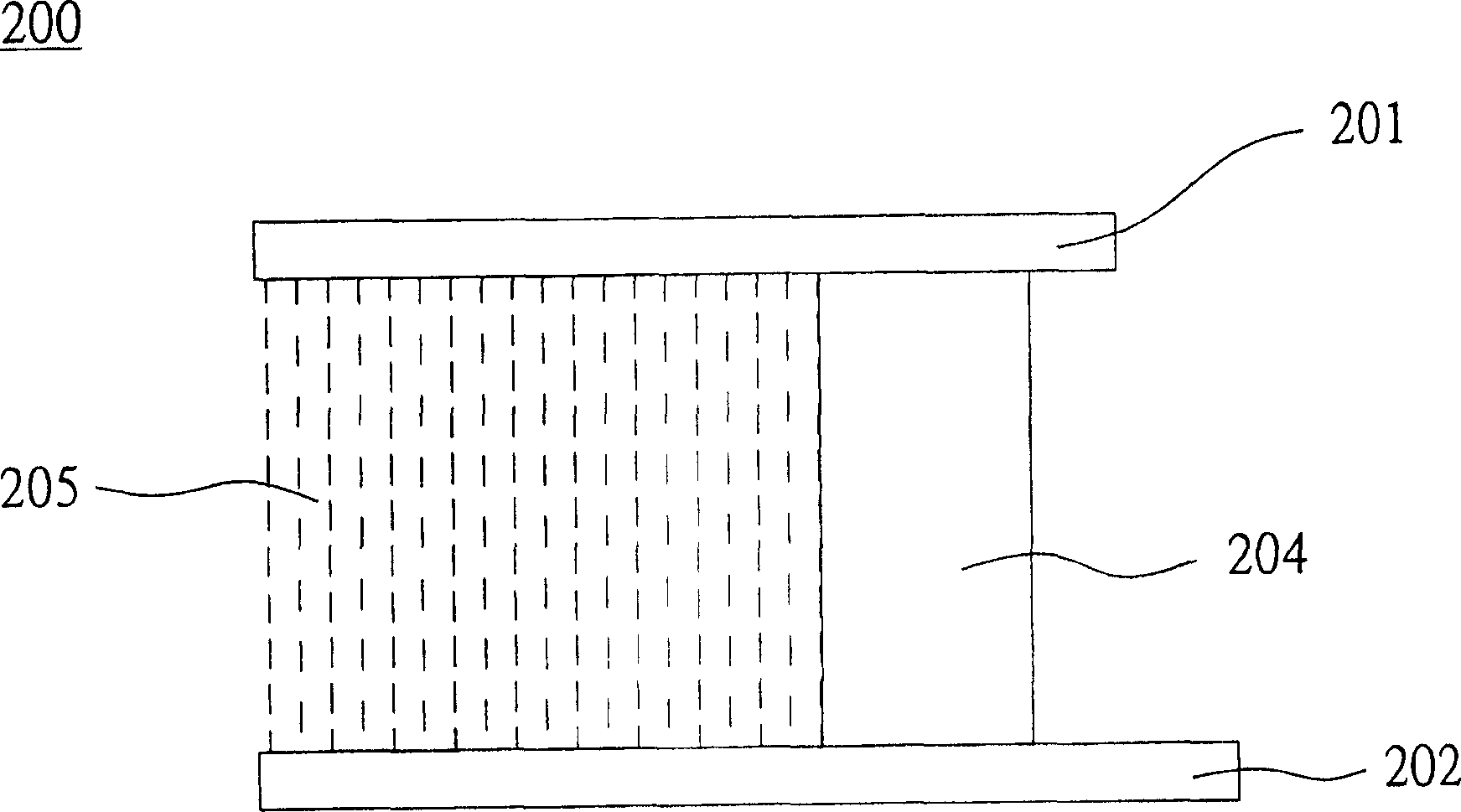
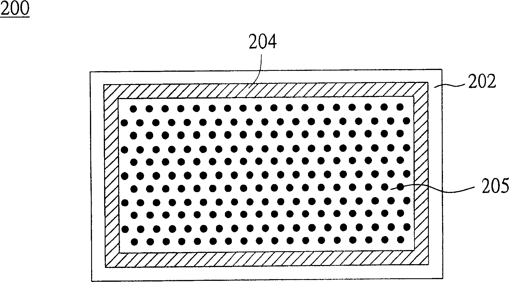
[0032] Please refer to Figure 2A , which depicts a side view of the display panel according to the first embodiment of the present invention. exist Figure 2A Among them, the display panel 200 includes a first substrate 201 , a second substrate 202 and a non-transparent sealant 204 . The first substrate 201 and the second substrate 202 can be a color filter substrate and a thin film transistor substrate respectively, or can be a thin film transistor substrate and a color filter substrate respectively. The non-transparent sealant 204 is generally a UV curable resin (UV Resin), or a thermal curable resin (Thermal Resin), or both UV curable resin and thermal curable resin. The second substrate 202 is arranged parallel to the first substrate 201 . Please refer to Figure 2B , Figure 2B What is depicted is a schematic diagram of coating the sealant of the first embodiment on the second substrate. Such as Figure 2B As shown, the non-transparent sealant 204 is coated on the...
no. 2 example
[0035] Please refer to Figure 3A and Figure 3B , Figure 3A Depicted is a side view of a second embodiment. Figure 3B What is depicted is a schematic diagram of coating the sealant on the second substrate. The display panel 300 includes a first substrate 301 , a second substrate 302 , a non-transparent sealant 304 and a black matrix 306 around the panel. The second substrate 302 is configured relative to the first substrate 301, and the non-transparent sealant 304 is coated on the periphery of the surface of the second substrate 302, and is in contact with the first substrate 301 when the first substrate 301 and the second substrate 302 are paired. catch. Wherein, the liquid crystal 305 is sealed between the first substrate 301 and the second substrate 302 . The composition of the non-transparent sealant 304 is the same as that of the non-transparent sealant 204 described in the first embodiment. The black matrix 306 around the panel is formed on the surface of the se...
PUM
 Abstract
Description
Claims
Application Information
 - R&D Engineer
- R&D Manager
- IP Professional
- Industry Leading Data Capabilities
- Powerful AI technology
- Patent DNA Extraction
Browse by: Latest US Patents, China's latest patents, Technical Efficacy Thesaurus, Application Domain, Technology Topic.
© 2024 PatSnap. All rights reserved.Legal|Privacy policy|Modern Slavery Act Transparency Statement|Sitemap