Technological installation matched with cooling pipe type low pressure synthesis tower

A technology of process equipment and synthesis tower, which is applied in the preparation of organic compounds, preparation of hydroxyl compounds, chemical instruments and methods, etc., can solve the problems of insufficient utilization of catalysts, differences in catalyst activity, and large consumption of catalysts, etc. Achieve catalyst activity protection, facilitate reaction, and save investment

Inactive Publication Date: 2006-08-30
ZHEJIANG UNIV OF TECH
View PDF1 Cites 2 Cited by
  • Summary
  • Abstract
  • Description
  • Claims
  • Application Information

AI Technical Summary

Benefits of technology

This new method described in this patented describes an improvement on existing methods such as those mentioned earlier. These improvements include reducing complexity during reactor construction, increasing efficiency at lower temperatures, improving performance over multiple stages, enhancing safety features, protecting equipment from damage caused by excessive heat exposure, etc., resulting in better overall process control and higher yields per unit area compared to older techniques like single column devices.

Problems solved by technology

This patented technical problem addressed in this patents relates to improving the efficiency and economy of producing lower pressures of m ethane through an economically efficient way that can be done without increasing costs or requiring extensive infrastructure expansions.

Method used


Image

  • Technological installation matched with cooling pipe type low pressure synthesis tower
  • Technological installation matched with cooling pipe type low pressure synthesis tower

Examples


Embodiment Construction

[0016] Combine below figure 2 The present invention is further described.

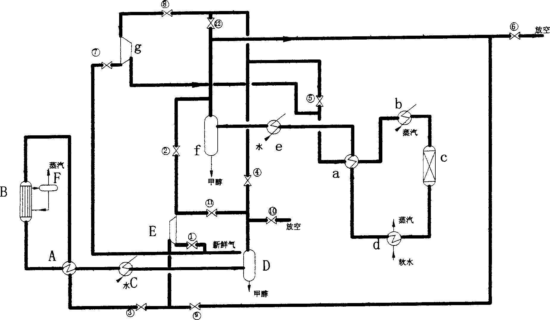
[0017] The low-pressure methanol synthesis device of the shell-and-tube synthesis tower system of the present invention consists of a heat exchanger (A), a shell-and-tube synthesis tower (B), a water cooler (C), an alcohol separator (D), a circulator (E) and a steam drum (F) consists of an independent production system connected by corresponding pipes and valves.

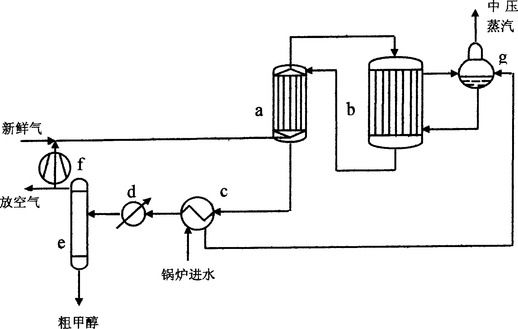
[0018] The low-pressure synthesis device of the cold tube type synthesis tower system of the present invention consists of a heat exchanger (a), a steam heater or an electric heater (b), a cold tube type synthesis tower (c), a waste heat boiler (d), and a water cooler (e). , an alcohol separator (f) and a circulation machine (g), connected by corresponding pipelines and valves to form an independent production system.

[0019] Adding some pipelines and valves can make the two systems into a series or parallel device, and the front and rear s


PUM


Abstract

The present invention relates to a process equipment matched with cold-tube type low-pressure synthesis tower. It adopts two production systems which can be series-connected or parallel-connected to make production. First stage adopts shell and tube type (or cold-tube type) synthesis tower and rear stage adopts cold-tube type (or shell and tube type) synthesis tower, also can completely adopt cold-tube type synthesis tower. Every synthesis tower can be an independent system respectively, and the described cold-tube type synthesis tower type can be single-tube baffled type and U-shaped tube type. Between two synthesis towers are mounted pipeline and valve for make regulation.

Description


Claims


Application Information

Patent Timeline
Owner ZHEJIANG UNIV OF TECH
Why Eureka
Try Eureka