Shaft drive for loom shafts

A technology of transmission device and drive device, which is applied in looms, textiles, dobbies, etc., can solve the problem of inflexibility of cam machines and achieve the effect of rapid response

Active Publication Date: 2006-09-20
GROZ BECKERT KG
View PDF2 Cites 2 Cited by
  • Summary
  • Abstract
  • Description
  • Claims
  • Application Information

AI Technical Summary

Problems solved by technology

But this cam machine

Method used


Image

  • Shaft drive for loom shafts
  • Shaft drive for loom shafts
  • Shaft drive for loom shafts

Examples


Example Embodiment

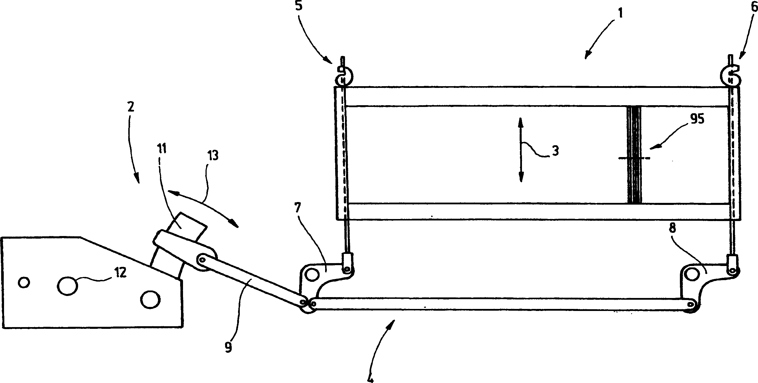
[0032] figure 1 The heald frame 1 and the associated heald frame transmission 2 are shown. The heald frame 1 is composed of a frame with a wire heald 95, and the frame moves up and down as indicated by the arrow 3 during the work. For transmission, a connecting rod 4 is used, which is connected to two or more parts 5 and 6 of the heald frame 1 and constitutes the output device of the heald frame transmission device 2. There are toggle levers 7, 8 belonging to the connecting rod 4. The toggle lever is connected to the heald frame 1 on the one hand and directly or indirectly with the tie rod and the pressure rod 9 on the other hand. The pull rod and the pressure rod are connected to the heald frame transmission 2, which for this purpose has a pendulum rod 11 that follows the swing motion at the output end. The heald frame transmission 2 is generated from the uniform rotational movement of the input shaft 12 figure 1 The reciprocating movement indicated by the arrow 13 is indicated b


PUM


Abstract

A new shaft drive provides for a switch-on and switch-off of individual heald shafts even at high working speeds. For this purpose switching pawls are provided which couple an eccentric with permanently revolving and/or back-and-forth oscillating disks. Measures for improving the controllability of such a clutch device are the control of the switching pawls by slot guides, associating bi-stabile biasing devices with the switching pawls and/or dividing the switching function into individual switching pawls ( 27 a , 27 b) which are associated individually with differently running disks ( 21, 22 ). Preferably, one of the two disks executes a continuous rotary motion, while the respective other disk performs only an oscillating motion which determines the heald shaft motion during the resting phases thereof.

Description


Claims


Application Information

Patent Timeline
Owner GROZ BECKERT KG
Why Eureka
Try Eureka