Liquid material arrangement method, color filter manufacturing method, and organic el display device manufacturing method

Active Publication Date: 2008-11-27
TOKYO ELECTRON LTD
View PDF6 Cites 2 Cited by
  • Summary
  • Abstract
  • Description
  • Claims
  • Application Information

AI Technical Summary

Benefits of technology

[0011]According to one aspect of the present invention, a liquid material arrangement method is performed for arranging a liquid material in a prescribed region on a substrate by causing a nozzle and the substrate to scan in relative manner and discharging the liquid material from the nozzle based on a dot pattern. The liquid material arrangement method comprises a first pattern generating step for generating a first dot pattern in which a first prescribed number of dots is set according to the prescribed region, a dot deleting step for deleting a second prescribed number of dots from the first prescribed number of dots to generate a second dot pattern, and a liquid material arranging step for arranging the liquid material based on the second dot pattern, wherein prohibited dots determined based on discharge information of the nozzle known or determined in advance are deleted with priority in the dot deleting step.
[0012]In the liquid material arrangement method of one aspect of the present invention, a second prescribed number of dots are deleted from a first dot pattern that has the first prescribed number of dots set so as to correspond to a prescribed region, a second dot pattern is generated, and the liquid material is arranged based on the second dot pattern. A determination is then made as to whether any of the abovementioned first prescribed number of dots are prohibited dots based on discharge information of the nozzles, dots that are determined to be prohibited dots are deleted with priority, and the second dot pattern is generated. The liquid material can therefore be arranged without performing liquid material discharge that is likely to cause defects. Since the second dot pattern is generated essentially by “selecting” dots for deletion from the plurality (first prescribed number) of dots under given conditions (discharge information), processing is simple even under complex conditions. The tot

Problems solved by technology

However, the nozzle (head) characteristics can vary from unit to unit, and the characteristics sometimes vary due to late-occurring factors and other causes, and the hardware conditions sometimes do not necessarily match the ideal model.
Howe

Method used


Image

  • Liquid material arrangement method, color filter manufacturing method, and organic el display device manufacturing method
  • Liquid material arrangement method, color filter manufacturing method, and organic el display device manufacturing method
  • Liquid material arrangement method, color filter manufacturing method, and organic el display device manufacturing method

Examples


first embodiment

Structure of Color Filter

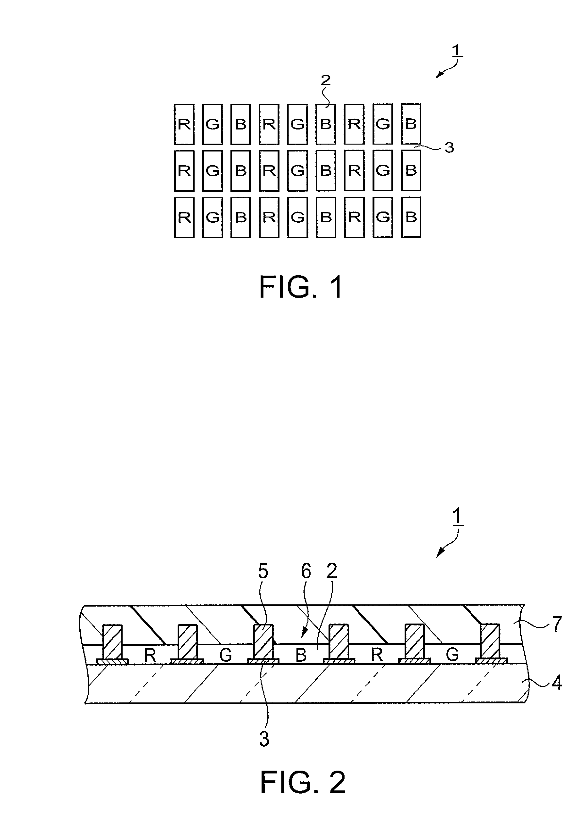
[0059]The structure of the color filter according to the present invention will first be described with reference to FIGS. 1 and 2. FIG. 1 is a plan view showing the configuration of the color filter. FIG. 2 is a sectional view showing the structure of the color filter.

[0060]The color filter 1 shown in FIGS. 1 and 2 is used in a color display panel, and has colored parts 2 that are formed so as to correspond to pixels of each color that include R (red), G (green), and B (blue) in the display panel; and light-blocking parts 3 that are formed in the regions between the colored parts 2. The colored parts 2 in the present embodiment have an arrangement and shape that correspond to a so-called striped pixel structure, but a different pixel structure may also be used. For example, a configuration may be adopted that is adapted to a structure that includes a color element other than R, G, and B, or to a delta structure.

[0061]The color filter 1 is provided with a glass

modification example 1

[0112]Modification Example 1 will next be described with reference to FIGS. 10, 13A, 15, and 16, with emphasis on the differences between Modification Example 1 and the previously described embodiment.

[0113]FIG. 15 is a diagram showing the conditions for selecting deleted dots according to Modification Example 1. FIG. 16 is a diagram showing an example of the second dot pattern according to Modification Example 1.

[0114]In Modification Example 1, deleted dots are selected in step S15 based on the conditions shown in FIG. 15. Specifically, dots that correspond to nozzles other than the nozzle that corresponds to the dots already targeted for deletion in step S115 are selected by the first condition. By setting such a condition, since dots corresponding to each of the nozzles are deleted in substantially uniform ratios, the usage frequency of the nozzles with respect to a single partitioned region 6 is appropriately distributed. This configuration makes it possible to prevent fluctuation

modification example 2

[0116]Modification Example 2 will next be described with reference to FIGS. 10, 13A, 17, and 18, with emphasis on the differences between Modification Example 2 and the previously described embodiment.

[0117]FIG. 17 is a diagram showing the conditions for selecting deleted dots according to Modification Example 2. FIG. 18 is a diagram showing an example of the second dot pattern according to Modification Example 2.

[0118]In Modification Example 2, deleted dots are selected in step S15 based on the conditions shown in FIG. 17. Specifically, dots that correspond to nozzles other than the nozzle that corresponds to the dots already targeted for deletion in step S15 are selected by the first condition, and dots of the third scan are selected by the second condition. By setting such conditions, dots corresponding to each of the nozzles are deleted in substantially uniform ratios, the usage frequency of the nozzles is appropriately distributed, the amount of the liquid material arranged in the


PUM


Abstract

A liquid material arrangement method includes performing a first pattern generating step, a dot deleting step, and a liquid material arranging step. The first pattern generating step includes generating a first dot pattern in which a first prescribed number of dots is set according to the prescribed region. The dot deleting step includes deleting a second prescribed number of dots from the first prescribed number of dots to generate a second dot pattern. The liquid material arranging step includes arranging a liquid material in a prescribed region on a substrate by causing a nozzle and the substrate to scan in relative manner and discharging the liquid material from the nozzle based on the second dot pattern. The performing of the dot deleting step further includes deleting at least one prohibited dot with priority with the prohibited dot being determined based on discharge information of the nozzle determined in advance.

Description


Claims


Application Information

Patent Timeline
Owner TOKYO ELECTRON LTD
Why Eureka
Try Eureka