Continuously welded vane

A technology for impellers and hubs, applied in the field of continuous welded impellers, to achieve high strength and high work efficiency

Inactive Publication Date: 2006-09-20
毛义庆
View PDF0 Cites 1 Cited by
  • Summary
  • Abstract
  • Description
  • Claims
  • Application Information

AI Technical Summary

Benefits of technology

In this new method for manufacturing an improved fan with better performance compared to existing techniques like spot welds or resistance wires used during production. By creating a strong and clear surface on both sides of each blade instead of just one side, it becomes stronger without being affected over time due to its higher power level. Additionally, there are fewer points where they may break down easily when hit against something causing damage. Overall, these technical improvements make fans safer from use even at their highest levels of energy consumption.

Problems solved by technology

This patented technical solution involves creation of impellers from metallic materials without causing any issues like heat distortions during production processes due to their complicated shapes. However, current methods involve expensive labor costs and wasteful resources compared to continuously welded solutions.

Method used


Image

  • Continuously welded vane

Examples


Embodiment Construction

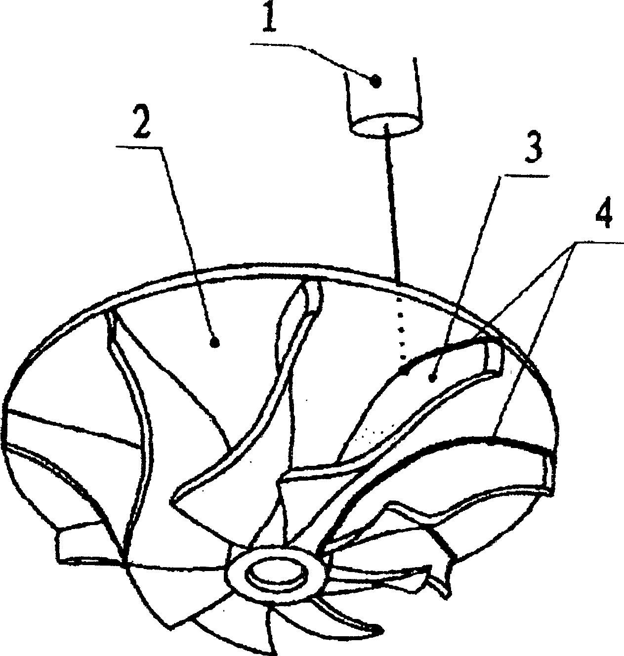
[0007] Below in conjunction with accompanying drawing and embodiment for further explanation: figure 1 The blade 3 and the hub 2 are made of sheet metal. The laser 1 focuses the laser beam on the joint between the blade 3 and the hub 2 from the other side of the hub 2 under the control of the computer, and along the blade 3 and the hub 2, a continuous weld 4 can be formed at this joint, and the blade 3 and the hub 2 are firmly connected. The joints between the plurality of blades 3 and the hub 2 are fixedly connected by a plurality of continuous welds 4 to form an impeller continuously welded by metal plates.


PUM


Abstract

The present invention discloses a continuously-welded blade wheel. It is composed of wheel hub made of metal plate and several blades. It is characterized by that the combined position of said wheel hub and blades is fixedly connected by utilizing continuous welded seam. Said welding method is implemented by adopting high-power laser continuous welding process.

Description


Claims


Application Information

Patent Timeline
Owner 毛义庆
Why Eureka
Try Eureka