Controller for electric power steering apparatus

An electric power steering and control device technology, which is applied to automatic steering control components, electric steering mechanisms, steering mechanisms, etc., can solve problems such as cost increase, and achieve the effects of low cost and improved handling feeling.

Inactive Publication Date: 2006-12-06
JTEKT CORP +1
View PDF1 Cites 6 Cited by
  • Summary
  • Abstract
  • Description
  • Claims
  • Application Information

AI Technical Summary

Benefits of technology

This technology describes how two separate circuits calculate the desired values of certain parameters during operation: one uses a specific algorithm while another checks if there are any changes made by the same algorithms or processes being done correctly. By doing these things quickly, the system becomes more accurate and reliable without requiring expensive components like CPU cores or ASIC devices. Additionally, when multiple processors work together they use less resources compared to traditional systems where each processor has its own set of instructions needed for calculating different quantities. Overall, this innovation improves the performance and reliability of electronic controllers such as EPSCUMS.

Problems solved by technology

This patented technical problem addressed in this patents relates to improving the accuracy and responsiveness of controlling electrically powered devices like automobiles during braking operations while minimizing costs associated therewith.

Method used


Image

  • Controller for electric power steering apparatus
  • Controller for electric power steering apparatus
  • Controller for electric power steering apparatus

Examples


Embodiment Construction

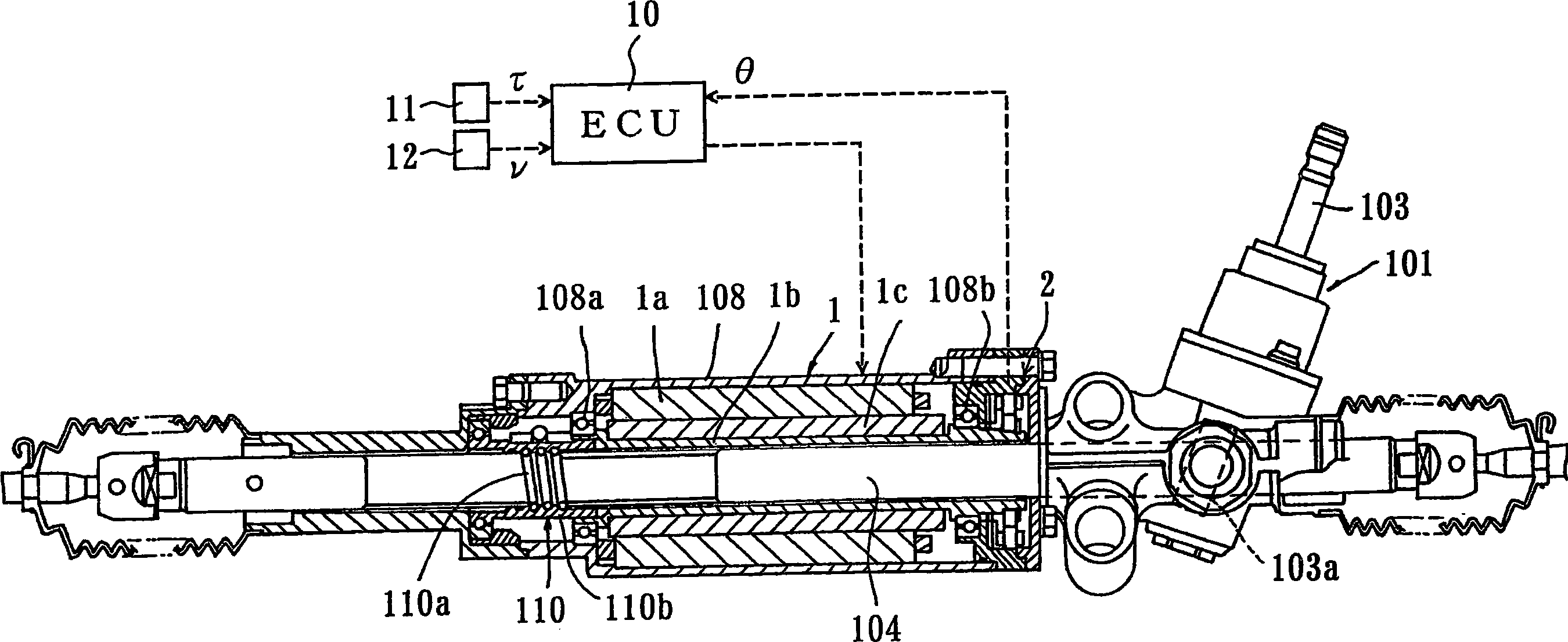
[0029] figure 1 The illustrated rack and pinion type electric power steering device 101 for a vehicle has a steering shaft 103 that is rotated by manipulation; a pinion 103a provided on the steering shaft 103; a rack 104 that meshes with the pinion 103a; A three-phase brushless motor for power 1. Both ends of the rack 104 are connected with steering wheels (not shown). As the steering pinion 103a rotates, the rack 104 moves in the long axis direction along the vehicle width direction, and the steering angle is changed by the movement of the rack 104 .

[0030] The motor 1 has a stator 1a including coils of U, V, and W phases fixed to a housing 108 covering a rack 104; a cylindrical rotor 1b rotatably supported on the housing 108 via bearings 108a, 108b. ; the magnet 1c attached to the rotor 1b; and the resolver 2 constituting a rotational position detection unit for detecting the rotational position of the rotor 1b, and the rack 104 is surrounded by the rotor 1b. The screw mec


PUM


Abstract

In a controller for an electric power steering apparatus, a target value calculation element, which calculates target values of the drive currents of a motor on the basis of a detected value of the steering torque, is constituted by a first integrated circuit provided in a chip. A drive signal value calculation element, which calculates drive signal values for driving the motor on the basis of the target values calculated by the target value calculation element, detected values of the drive currents of the motor, and a detected value of the rotary position of a rotor of the motor, is constituted by a second integrated circuit provided in another chip from the chip. A driving element drives the motor in accordance with the drive signal values. The first integrated circuit is connected communicably to the second integrated circuit. The calculation cycle of the drive signal values is set to be shorter than the calculation cycle of the target values.

Description


Claims


Application Information

Patent Timeline
Owner JTEKT CORP
Why Eureka
Try Eureka