Slide assembly for a firearm

a slide assembly and firearm technology, applied in the field of firearms, can solve the problems of damage to the mounting system of early sights, impractical for tactical and law enforcement use, and difficulty in milling the recess as deep as desired without interfering with the internal working components of the slide, so as to reduce or eliminate interference

Active Publication Date: 2021-07-20
SHADOW SYST LLC
View PDF2 Cites 7 Cited by
  • Summary
  • Abstract
  • Description
  • Claims
  • Application Information

AI Technical Summary

Benefits of technology

The present inventors have developed ways to make it easier by allowing certain parts inside slides to be placed closer together when they are being assembled into an article like clothing. This helps prevent any unwanted things from getting stuck during assembly process. Additionally, there can also include features that allow users to easily change their own look on them while still maintaining secure attachment over time. These technical improvements improve the overall appearance quality of such products.

Problems solved by technology

Technological Problem: Current Opacity Sight Mountings For Handheld Weapon Spikes require significant time and labor costs while requiring modification beforehand due to their limited adjustability. Additionally, current solutions involve bulky brackets attached directly behind the firearm handle making it hard to see clearly during combat situations where weapon explosion occurs. There has been proposed various ways to modify existing guns equipped with opacities like dye lights called "redoscopies," allowing soldiers to look down onto targets even if there was no light source available. These techniques reduce the risk associated with striking weapons and improve safety standards.

Method used


Image

  • Slide assembly for a firearm
  • Slide assembly for a firearm
  • Slide assembly for a firearm

Examples


Embodiment Construction

[0045]Reference will now be made in detail to the various exemplary embodiments of the subject disclosure illustrated in the accompanying drawings. Wherever possible, the same or like reference numbers will be used throughout the drawings to refer to the same or like features. It should be noted that the drawings are in simplified form and are not drawn to precise scale. Certain terminology is used in the following description for convenience only and is not limiting. Directional terms such as top, bottom, left, right, above, below and diagonal, are used with respect to the accompanying drawings. The term “distal” shall mean away from the center of a body. The term “proximal” shall mean closer towards the center of a body and / or away from the “distal” end. The words “inwardly” and “outwardly” refer to directions toward and away from, respectively, the geometric center of the identified element and designated parts thereof. Such directional terms used in conjunction with the following


PUM


Abstract

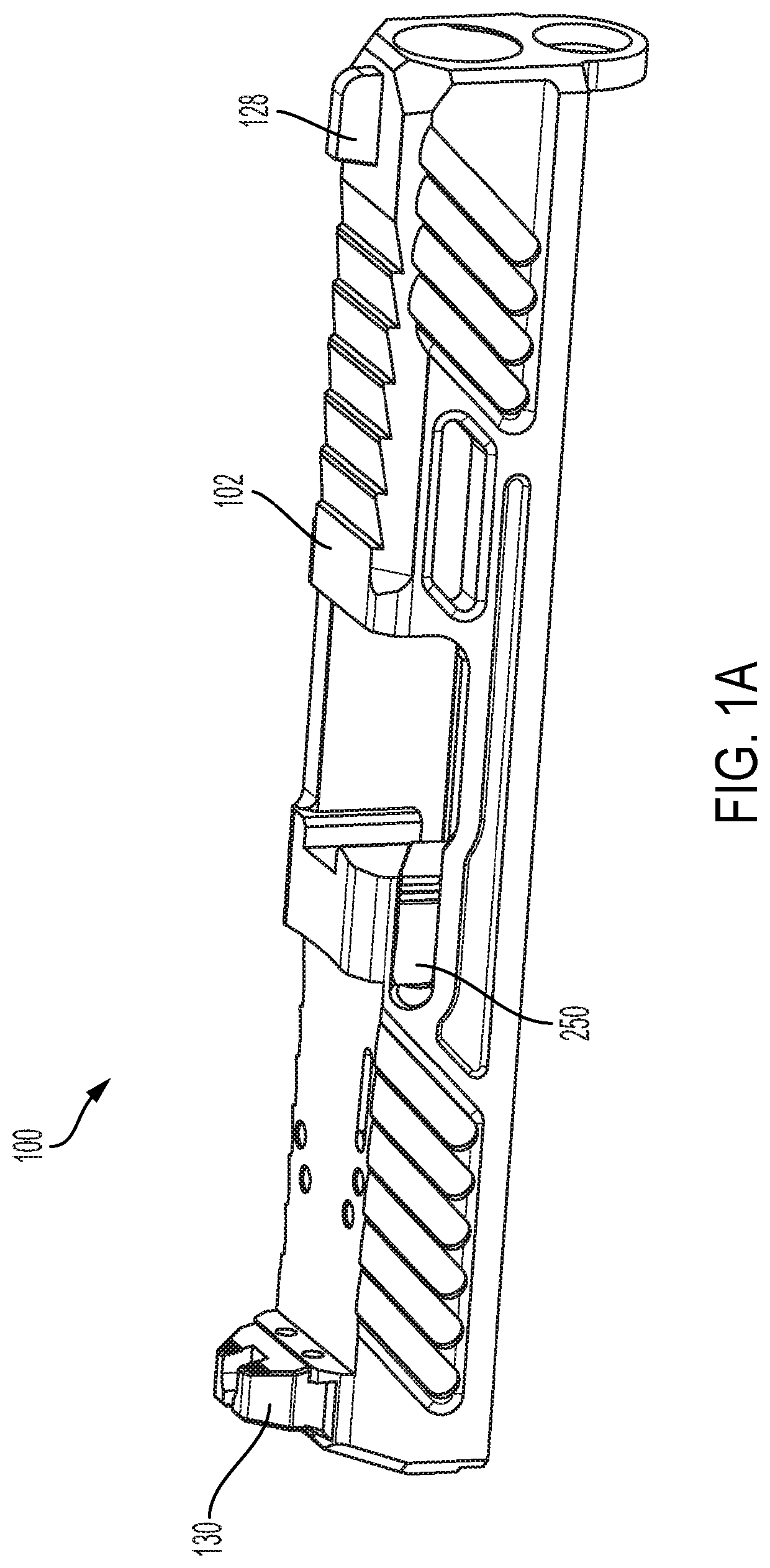
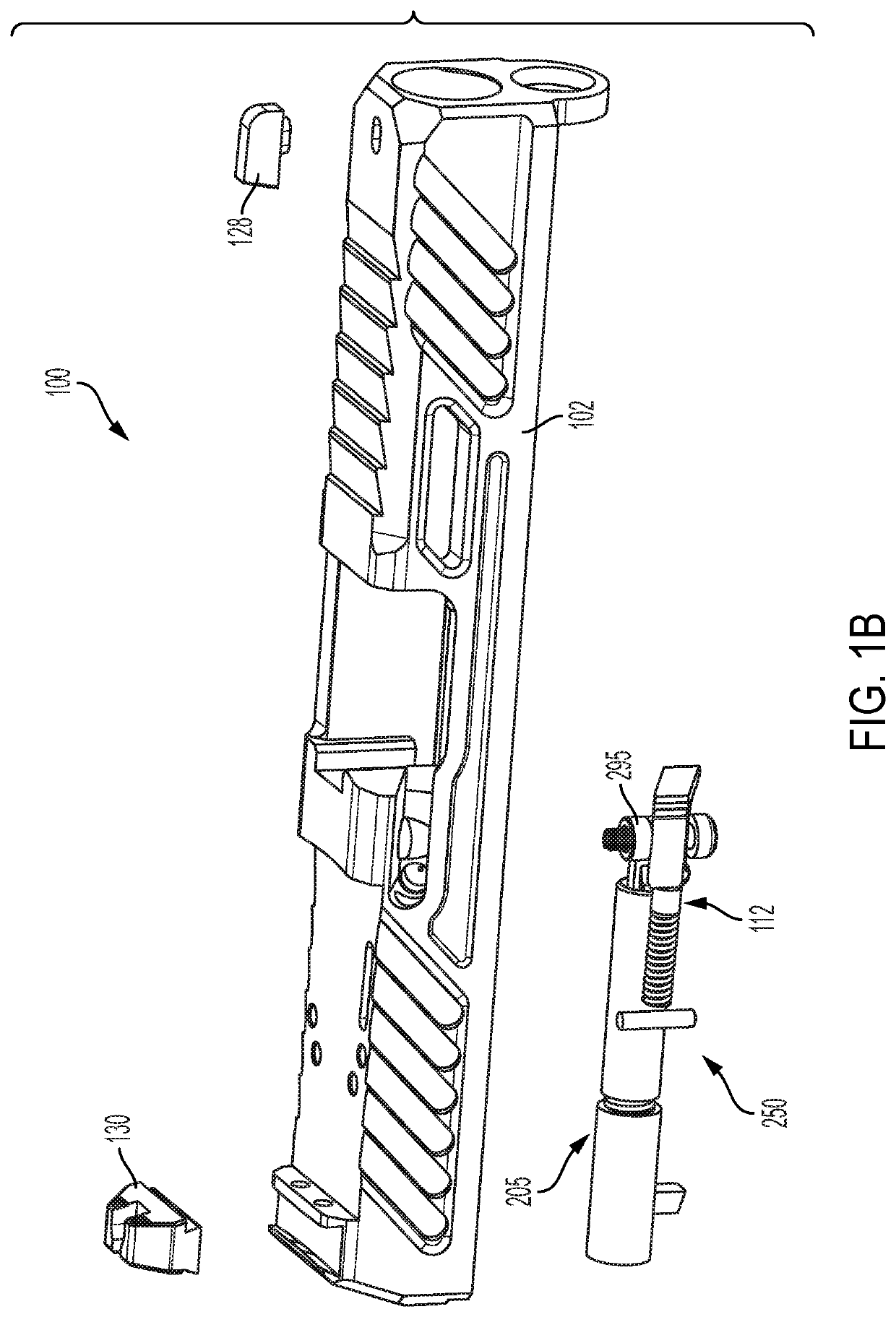
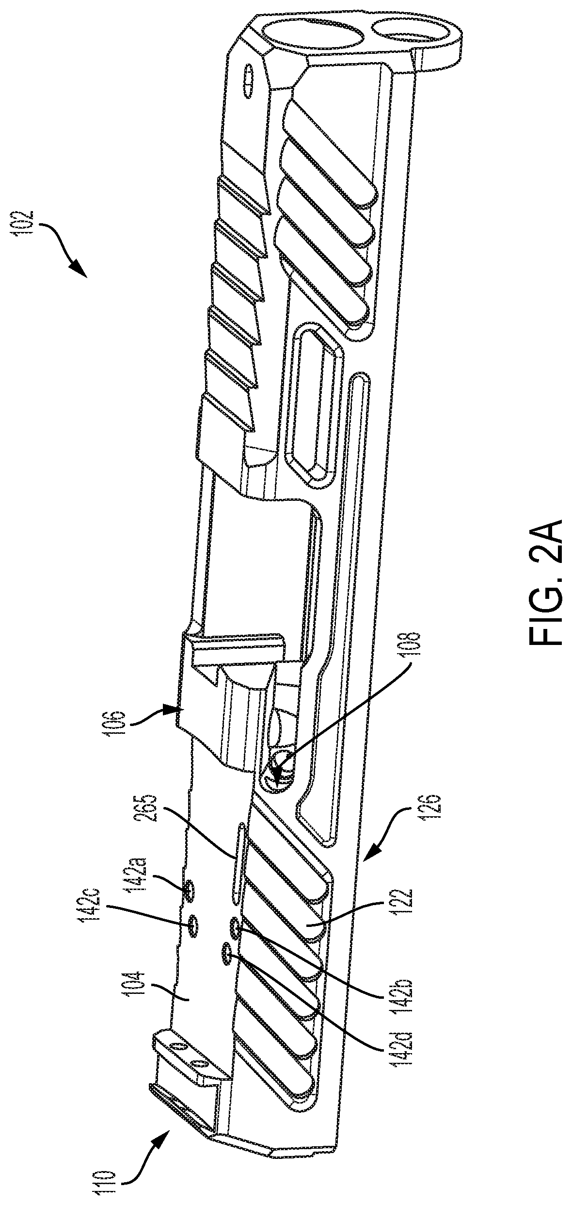
A slide assembly for a firearm comprising a slide and an extractor assembly is provided. The slide includes a mounting recess about a top side of the slide, and a housing recess about a proximal end of the slide. The extractor assembly is mounted within the housing recess and includes a distal end for engaging a cartridge and a proximal end opposite the distal end. The proximal end terminates at a position adjacent about a mid-portion of the mounting recess. One or more retaining holes are provided within a proximal region of the mounting recess spaced from the proximal end of the extractor assembly. Firearm sights are attachable to the mounting recess via fasteners engaging the retaining holes. The retaining holes are arranged such that they do not interfere with the extractor assembly or other components within the housing recess of the slide.

Description


Claims


Application Information

Patent Timeline
Owner SHADOW SYST LLC
Why Eureka
Try Eureka