Machine tool cutting force simulation loading device

A loading device and cutting force technology, applied in the direction of metal processing equipment, metal processing machinery parts, measuring/indicating equipment, etc., can solve the problems of complex structure and small load, and achieve wide applicability, wide load range and simple structure Effect

Active Publication Date: 2014-04-23
通用技术齐齐哈尔二机床有限责任公司
View PDF5 Cites 8 Cited by
  • Summary
  • Abstract
  • Description
  • Claims
  • Application Information

AI Technical Summary

Benefits of technology

This technology allows for easier experimentation with machining machines that use hydrauled systems or other methods like ball milling instead of traditional techniques such as grinding wheels. By adding one set of force from both directions into these hydrified cylindrical devices, it becomes possible to simulate varying levels of stress during turning operations without having to change the fluid's properties overall. It also makes it easy to control how much weight they are able to hold while working around curved surfaces effectively.

Problems solved by technology

This patented technical problem addressed in this patents relates to testing how well a machining center's spindles can withstand heavy usage without losing their effectiveness or causing damage during prolonged periods of time due to excessive thermal energy generated by them. Current methods involve performing static loadings that require significant materials being discarded after each measurement has been completed.

Method used


Image

  • Machine tool cutting force simulation loading device
  • Machine tool cutting force simulation loading device
  • Machine tool cutting force simulation loading device

Examples


Embodiment Construction

[0012] The present invention will be further described below in conjunction with accompanying drawing:

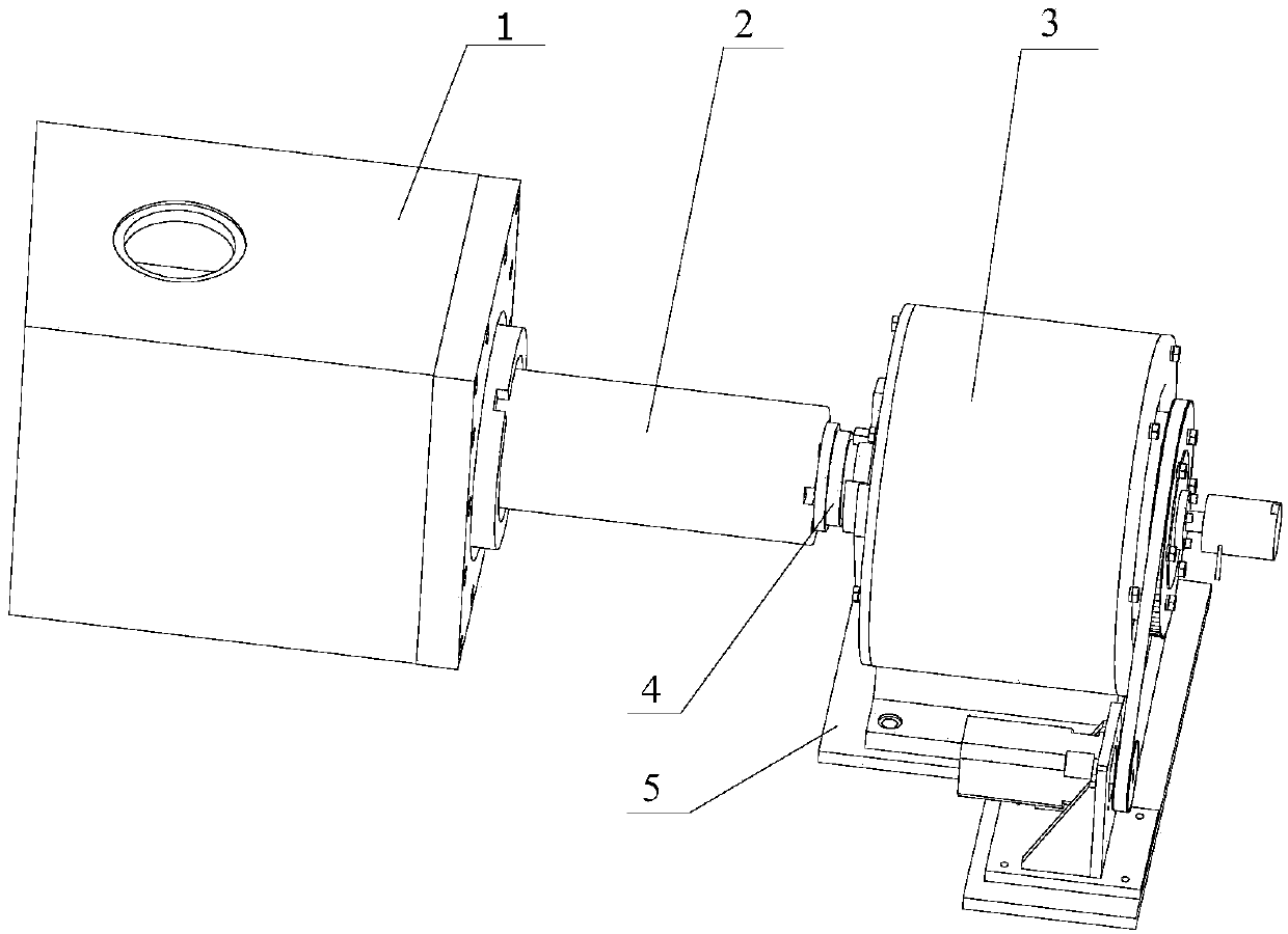
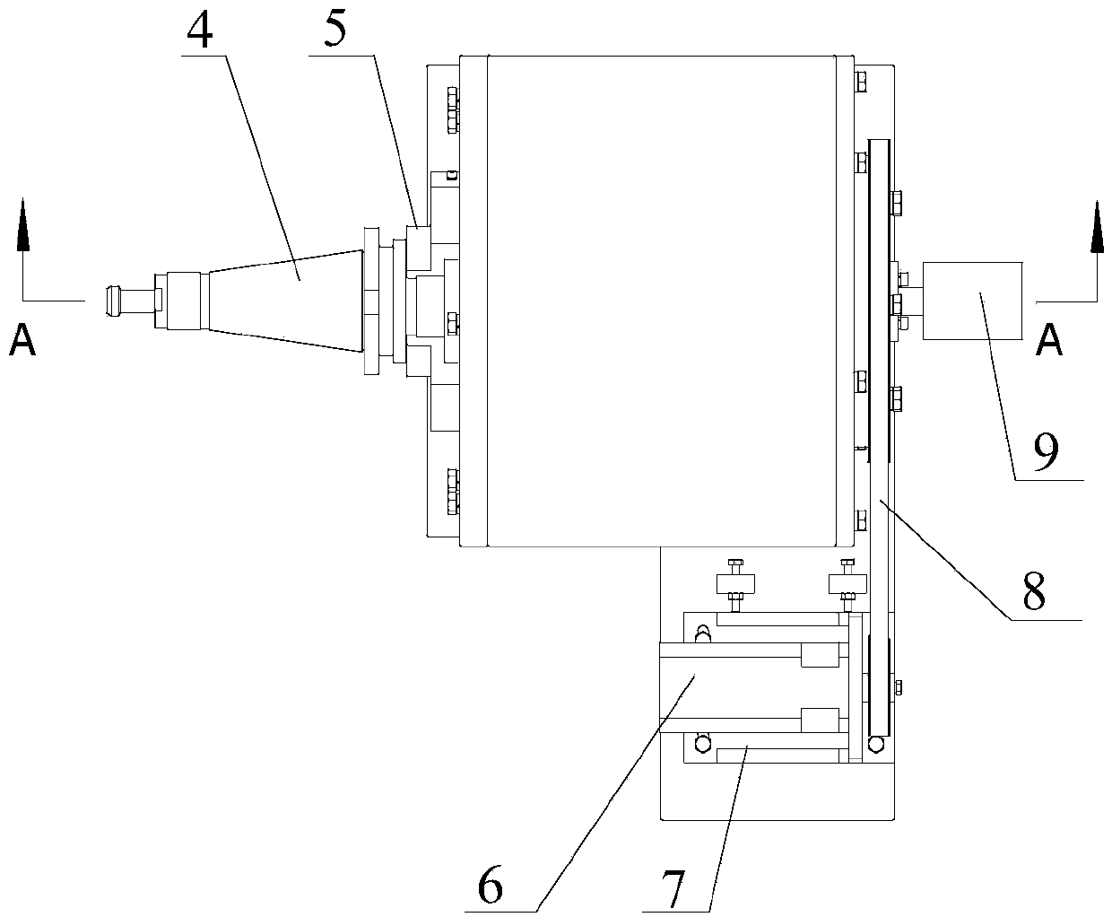
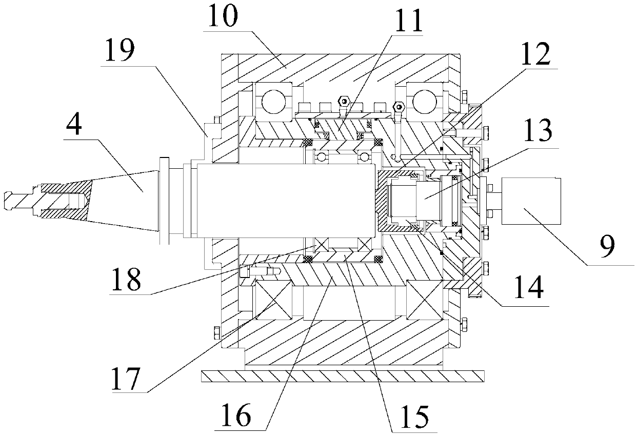
[0013] Depend on Figure 1 to Figure 3 As shown, a cutting force simulation loading device for a machine tool includes a loading mandrel 4. During the experiment, the loading mandrel 4 drives the entire loading device 3 to be connected to the main shaft 2 in the headstock 1. A platform 5 is provided at the bottom of the loading device 3. A servo motor 6 is fixed on the platform 5 through a motor support 7 . The right end of the loading mandrel 4 is placed in the main support 10, and the outside of the loading mandrel 4 is connected with a radial bearing sleeve 15 through a rolling bearing B18, and the outside of the radial bearing sleeve 15 is provided with a rotating body 16. There is a groove, and a radial hydraulic cylinder 11 is built in the groove, and the piston rod of the radial hydraulic cylinder 11 abuts on the outer surface of the radial bearing sleeve 15 . The rot


PUM


Abstract

Disclosed is a machine tool cutting force simulation loading device so as to mainly solve the problems that prior machine tool cutting force simulation loading devices are complicated in structure, small in load and not suitable for experimenting on large high-speed numerically-controlled machine tools. The device is characterized in that the outside of a loading mandrel (4) is connected with a radial bearing sleeve (15) through rolling bearings B (18), a rotary element (16) is arranged on the outside of the radial bearing sleeve (15), a radial hydraulic cylinder (11) is arranged in a groove of the rotary element (16), a piston rod of the radial hydraulic cylinder (11) abuts against the outer surface of the radial bearing sleeve (15), and the rotary element (16) is connected with a servo motor (6) through a belt (8). An axial bearing sleeve (12) is arranged at the right end of the loading mandrel (4), and an axial hydraulic cylinder (13) is arranged in the axial bearing sleeve (12). The device has the advantages of being simple in structure, large in load range and applicable to machine tools of various types.

Description


Claims


Application Information

Patent Timeline
Owner 通用技术齐齐哈尔二机床有限责任公司
Why Eureka
Try Eureka