Soil sampling device for highway engineering road and use method thereof

A technology for engineering and road use, which is applied in the field of soil sampling devices for road engineering, can solve the problems of affecting the sampling effect, sampling equipment penetration, and low sampling efficiency, so as to improve drilling efficiency, reduce difficulty, and reduce manpower The effect of consumption

Pending Publication Date: 2021-09-17
谭小波
View PDF6 Cites 8 Cited by
  • Summary
  • Abstract
  • Description
  • Claims
  • Application Information

AI Technical Summary

Benefits of technology

This patented technology uses special tools called squares rods, drilled bits, wires/cords, pliers, screws, etc., which are used together with an apparatus called a machine tool (M) controlled by computer programs. These machines work like car engines but they have certain technical features: 1) They use rotating saw blades instead of traditional methods such as handheld power tools, 2) It allows for quick changes between different types of materials without stopping it from working on them again, 3) By utilizing specific techniques, M's can crunch rocks faster than usual, 4) Using these tools during drills helps prevent wear and tear on equipment, reducing maintenance costs.

Problems solved by technology

This patented describes an improved way to collect data from excavated materials such as rocks that have been found near roads. However existing methods require manual movement over long distances due to their high cost and complexity. Additionally, these techniques may result in contamination issues if they come into direct physical contact between different parts of the material being collected.

Method used


Image

  • Soil sampling device for highway engineering road and use method thereof
  • Soil sampling device for highway engineering road and use method thereof
  • Soil sampling device for highway engineering road and use method thereof

Examples


Embodiment Construction

[0033] The following will clearly and completely describe the technical solutions in the embodiments of the present invention with reference to the accompanying drawings in the embodiments of the present invention. Obviously, the described embodiments are only some, not all, embodiments of the present invention.

[0034] In describing the present invention, it should be understood that the terms "upper", "lower", "front", "rear", "left", "right", "top", "bottom", "inner", " The orientation or positional relationship indicated by "outside", etc. is based on the orientation or positional relationship shown in the drawings, and is only for the convenience of describing the present invention and simplifying the description, rather than indicating or implying that the referred device or element must have a specific orientation, so as to Specific orientation configurations and operations, therefore, are not to be construed as limitations on the invention.

[0035] refer to Figure 1-7


PUM


Abstract

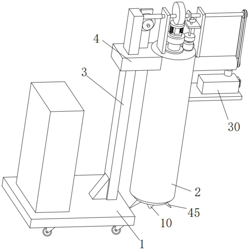
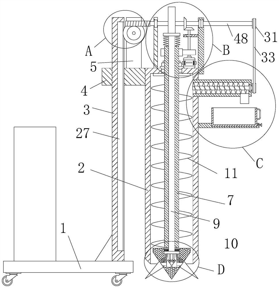
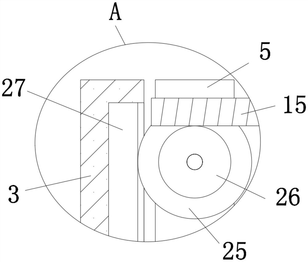
The invention relates to the technical field of highway construction, and discloses a soil sampling device for a highway engineering road and a using method thereof. The soil sampling device for the highway engineering road comprises a base and a sampling barrel; a supporting plate is fixedly installed on one side of the top of the base; the bottom of the sampling barrel is open; a sleeve plate is fixedly installed on one side of the sampling barrel; the sleeve plate sleeves the outer side of the supporting plate in a sliding mode; a motor is fixedly mounted at the top of the sampling barrel; a circular hole is formed in the top of the sampling barrel; a cylinder is rotatably mounted in the circular hole; a square hole is formed in the top end of the cylinder; a square rod is slidably mounted in the square hole; and a drill bit is arranged at the bottom end of the square rod. The device is reasonable in design, the drill bit is driven to rotate at a high speed and vibrate up and down while moving downwards at a low speed to drill holes in the ground, a hard soil layer can be conveniently drilled, manpower consumption is reduced, and drilled soil is conveyed into a collecting frame to be collected and stored, so automatic sampling of the soil is achieved, and the sampling work efficiency is improved.

Description


Claims


Application Information

Patent Timeline
Owner 谭小波
Why Eureka
Try Eureka