Multi-branched catheter-introducer tube

a catheter and intravenous technology, applied in the direction of dilators, surgery, guide needles, etc., can solve the problems of large physical burden on patients and a lot of tim

Inactive Publication Date: 2005-11-03
USCI JAPAN
View PDF2 Cites 3 Cited by
  • Summary
  • Abstract
  • Description
  • Claims
  • Application Information

AI Technical Summary

Benefits of technology

The technical effect that this new design solves with current methods for introducing blood vessels into arteries during medical procedures such as angioplasty or stenosis treatments.

Problems solved by technology

This patented technical problem addressed in this patents describes how current methods involve inserting multiple guide wires that can be challenging when treating vascular disease caused by obstructive plaque buckling around narrowings like those associated with coronary vessels. Current techniques require either use of more invasively treated devices or prolong exposure times under fluoroscopy conditions making it necessary to perform these procedures frequently. Additionally, there has been concern about potential complications including necrosis of healthy parts near areas where they might cause further harm if repeated insertions were needed over several days after surgery.

Method used


Image

  • Multi-branched catheter-introducer tube
  • Multi-branched catheter-introducer tube
  • Multi-branched catheter-introducer tube

Examples


Embodiment Construction

[0041] Now a particular embodiment of the present invention shown in the drawings will be described.

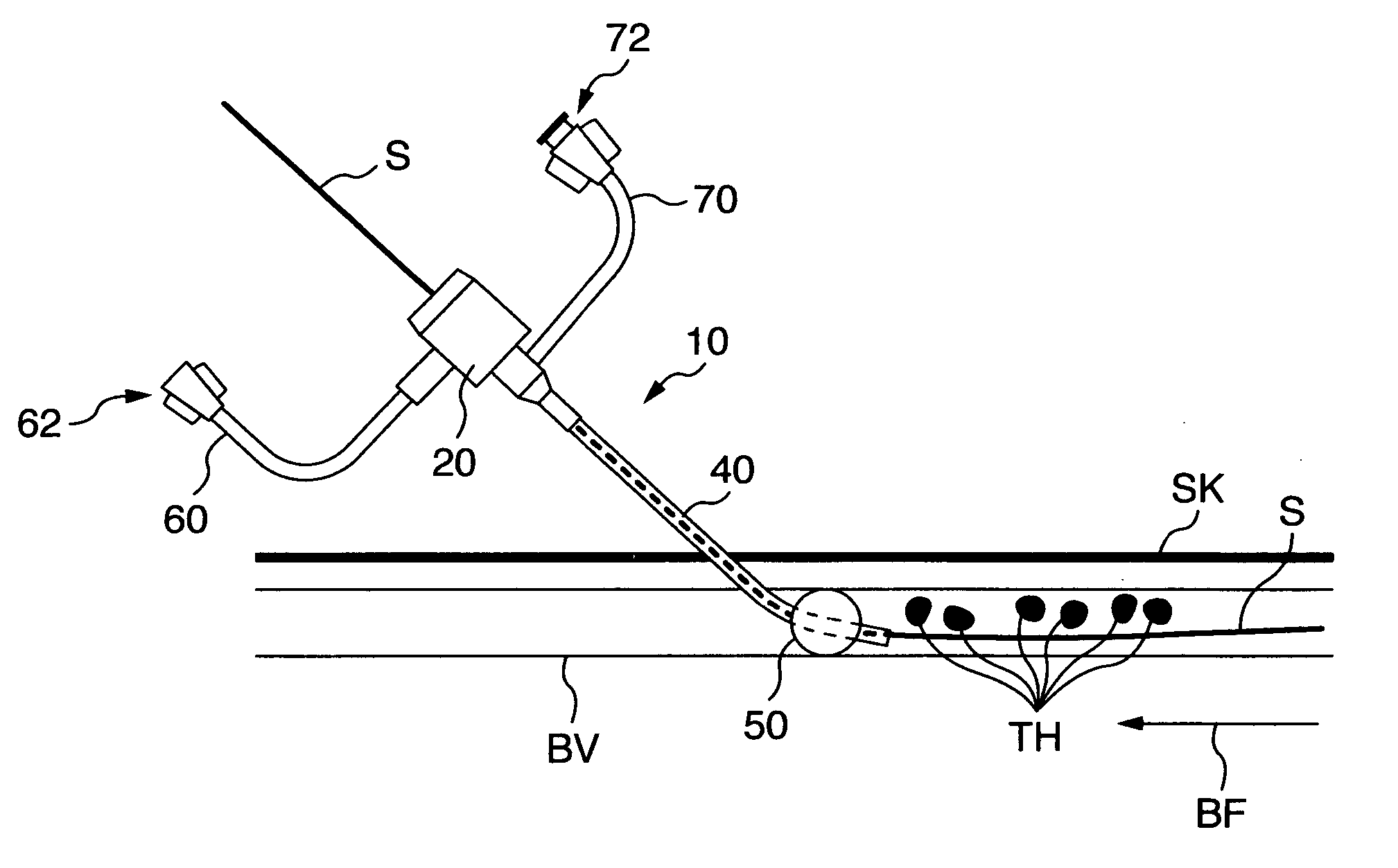
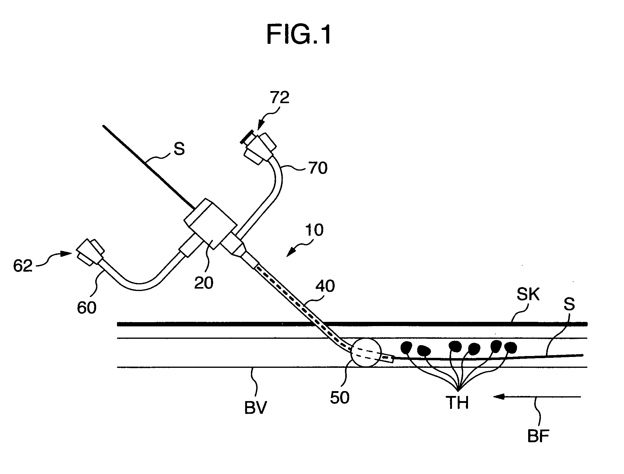
[0042]FIG. 1 schematically shows a state in which a percutaneous intubation angioplasty is being carried out with utilization of a multi-branched catheter-introducer tube 10 as one embodiment of the present invention. While the shape and structure of the multi-branched catheter-introducer tube 10 will be described later, a balloon catheter (a catheter shaft S) is shown as having been inserted into a blood vessel BV with utilization of the multi-branched catheter-introducer tube 10. A main conduit 40 of the multi-branched catheter-introducer tube 10 has been inserted into the blood vessel against a blood flow BF, and as a result of a vasodilator treatment by the balloon catheter, floating debris TH such as thrombus debris have been released into the blood flow from a diseased part to flow toward the main conduit 40. However, since a blood flow stopper balloon 50 provided on a distal end


PUM


Abstract

A multi-branched tube has a check valve structure, a main conduit adapted to be inserted into a blood vessel with its distal end, a first port tube leading to an inner chamber in the check valve structure, and a second port tube connected to the check valve structure. A blood flow stopper balloon is mounted on an outer periphery of the main conduit at a portion closer to its distal end. The main conduit has a first guide bore and a second guide bore, which are two separate guide bores. The blood flow stopper balloon is adapted to be inflated/deflated by a pressure of a fluid supplied thereinto through the second port tube and the second guide bore. Thrombus debris or the like in the blood vessel can be drawn and removed together with the blood through the first port tube, the inner chamber and the first guide bore.

Description


Claims


Application Information

Patent Timeline
Owner USCI JAPAN
Why Eureka
Try Eureka