Sealing system

a sealing system and sealing technology, applied in mechanical equipment, piston rings, transportation and packaging, etc., can solve the problems of reducing the effectiveness of sealing, affecting the lubrication of the bushing, and affecting so as to facilitate the lubrication effect of the bushing

Inactive Publication Date: 2006-02-02
CATERPILLAR INC
View PDF28 Cites 30 Cited by
  • Summary
  • Abstract
  • Description
  • Claims
  • Application Information

AI Technical Summary

Benefits of technology

This patented describes two aspects: 1. A bushing used for various purposes such as transmitting signals between devices without interference from other signal sources like electromagnetic waves. It also helps prevent damage caused by external factors during use. Additionally it can be easily moved around within its housing when needed.

Problems solved by technology

This patented technical problem addressed in this patents relates to improving the durability and performance of end surface sealed systems (ESS) in extreme conditions where they can come into physical contact with other parts due to movement caused by factors like temperature changes. Existing solutions involve adding layers made up mostly of chrome oxide onto these surfaces which also wear down over time, leading to leakages and decreased lifetimes.

Method used


Image

  • Sealing system
  • Sealing system
  • Sealing system

Examples


Embodiment Construction

[0012] Reference will now be made in detail to exemplary embodiments that are illustrated in the accompanying drawings. Wherever possible, the same reference numbers will be used throughout the drawings to refer to the same or like parts.

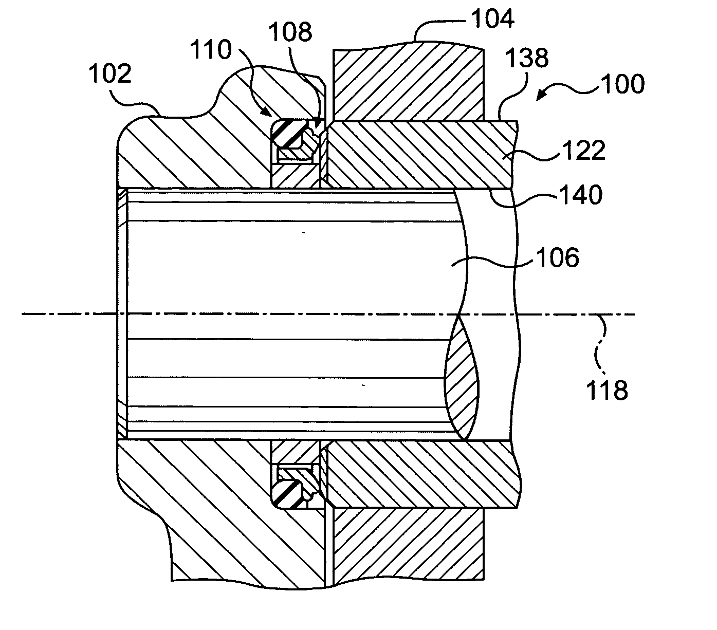
[0013]FIG. 1 shows an exemplary embodiment of one end of a track joint 100 of an endless track for a track-type work machine. The track joint 100 includes first and second pivotally interconnected overlapping links 102, 104, a track pin 106, and a sealing system 108. The links 102, 104 extend from the track joint 100 and connect to adjacent track joints (not shown) to create a track for a track-type work machine.

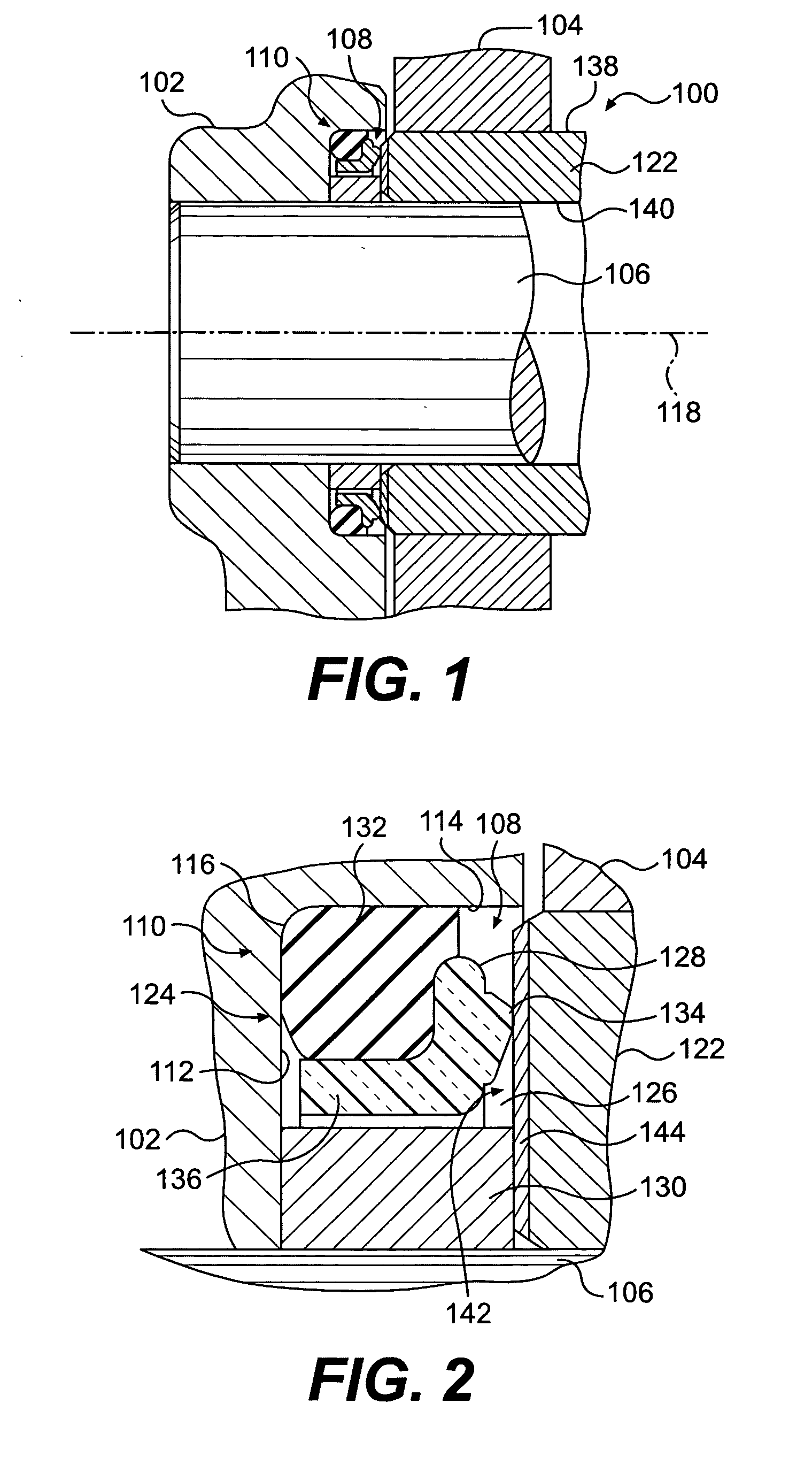
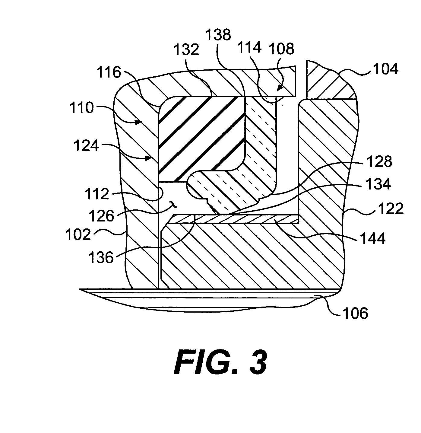
[0014]FIG. 2 is an enlargement of the track joint 100 shown in FIG. 1. As best seen in FIG. 2, the first link 102 includes a counter-bore 110 that is defined by an axially outwardly facing bore face 112, a cylindrical surface 114, and a corner portion 116.

[0015] The sealing system 108 is disposed intermediate the links 102, 104 and may be co


PUM


Abstract

A bushing includes an interior surface, an exterior surface, a first end, and a second end. An end face forms at least part of each of the first end and the second end. At leaset one of the exterior surface and the end face includes a sealing surface formed at least in part of a coating including a material having a hardness level greater than about 1200 Knoop. The sealing surface has a thickness greater than about 35 microns and an average roughness (Ra) less than about 0.25 micron. In one embodiment, the bushing may be used on an endless track for a track-type work machine.

Description


Claims


Application Information

Patent Timeline
Owner CATERPILLAR INC
Why Eureka
Try Eureka