Connecting rod assembly for an internal combustion engine and method of manufacturing same

a technology of connecting rods and internal combustion engines, which is applied in the direction of connecting rod bearings, manufacturing tools, machines/engines, etc., can solve the problems of engine failure, excess material along the small end of the connecting rod assembly, and impose an additional step in the manufacturing process that is costly and labor-intensive, so as to reduce the width configuration, reduce the moment force, and streamline manufacturing

Inactive Publication Date: 2006-05-18
MAHLE IND
View PDF43 Cites 14 Cited by
  • Summary
  • Abstract
  • Description
  • Claims
  • Application Information

AI Technical Summary

Benefits of technology

The present invention simplifies the production process while minimizing any potential issues such as defects or imperfections on the connection rod used in the manufacturing process. It also improves the quality control of the final product due to its elimination of the need for a deburring step before mounting the bushing. Additionally, it reduces stress force on the connection rod itself, resulting in less likely deformation and increased durability. This results in improved performance and reliability of the overall connected component system.

Problems solved by technology

The technical problem addressed in this patent is how to efficiently produce a connection rod assembly with a stepped small end without requiring a separate deburring process, while maintaining sufficient strength and durability over time.

Method used


Image

  • Connecting rod assembly for an internal combustion engine and method of manufacturing same
  • Connecting rod assembly for an internal combustion engine and method of manufacturing same
  • Connecting rod assembly for an internal combustion engine and method of manufacturing same

Examples


Embodiment Construction

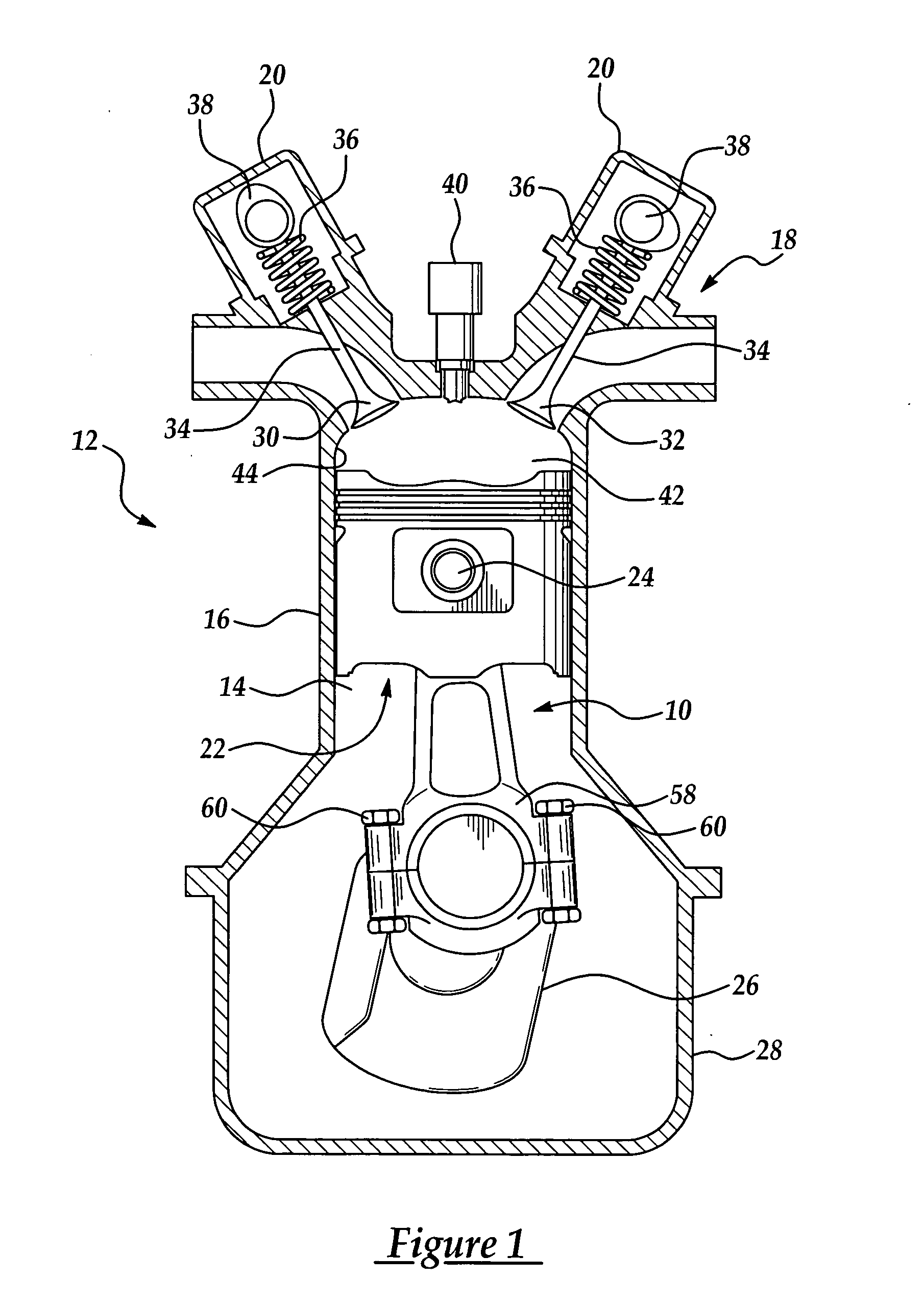
[0031] A connecting rod assembly manufactured pursuant to the method of the present invention is generally indicated at 10 throughout the figures, where like numbers are used to designate like structures throughout the drawings. As shown in FIG. 1, the present invention is particularly adapted for use in an internal combustion engine, generally indicated at 12. In this case, the assembly 10 of the present invention is illustrated in connection with a single cylinder 14 of an internal combustion engine 12 having a dual-overhead cam arrangement. Those having ordinary skill in the art will appreciate that the engine 12 is but one of the many internal combustion engines with which the present invention may be employed. By way of example, the present invention may be employed to manufacture a connecting rod assembly used in a two-stroke or four-stroke engine. The cylinders may be arranged in an in-line, v-shaped, or flat manner or in any other manner commonly known in the art. The present i


PUM

PropertyMeasurementUnit
Temperatureaaaaaaaaaa
Diameteraaaaaaaaaa
Widthaaaaaaaaaa

Abstract

The present invention relates to a connecting rod assembly and method of manufacturing same. The method includes defining a small end of a connecting rod having a terminal end and defining a pin bore extending through the small end. A pair of channels is forged on opposite sides of the small end, such that each of the channels is substantially perpendicular to the pin bore. A bushing having a contact surface including at least partially annular grooves and opposed distal ends is subsequently formed and installed into the pin bore of the small end. Following installation of the bushing, the connecting rod is machined to reduce the width of the small end between each channel and the terminal end to where at least a portion of the grooves are disposed along the distal ends to reduce the need to deburr the area adjacent the pin bore.

Description


Claims


Application Information

Patent Timeline
Owner MAHLE IND
Why Eureka
Try Eureka