In-situ removal of electrolyte from gas oxidizer
a gas oxidizer and electrolyte technology, applied in the field of fuel cell systems, can solve the problems of increasing the pressure drop across the catalyst block, increasing the difference between the pressure of the anode exhaust stream and the cathode inlet stream, and a larger difference in temperature distribution at one end of the catalyst block
- Summary
- Abstract
- Description
- Claims
- Application Information
AI Technical Summary
Benefits of technology
Problems solved by technology
Method used
Image

Examples
second embodiment
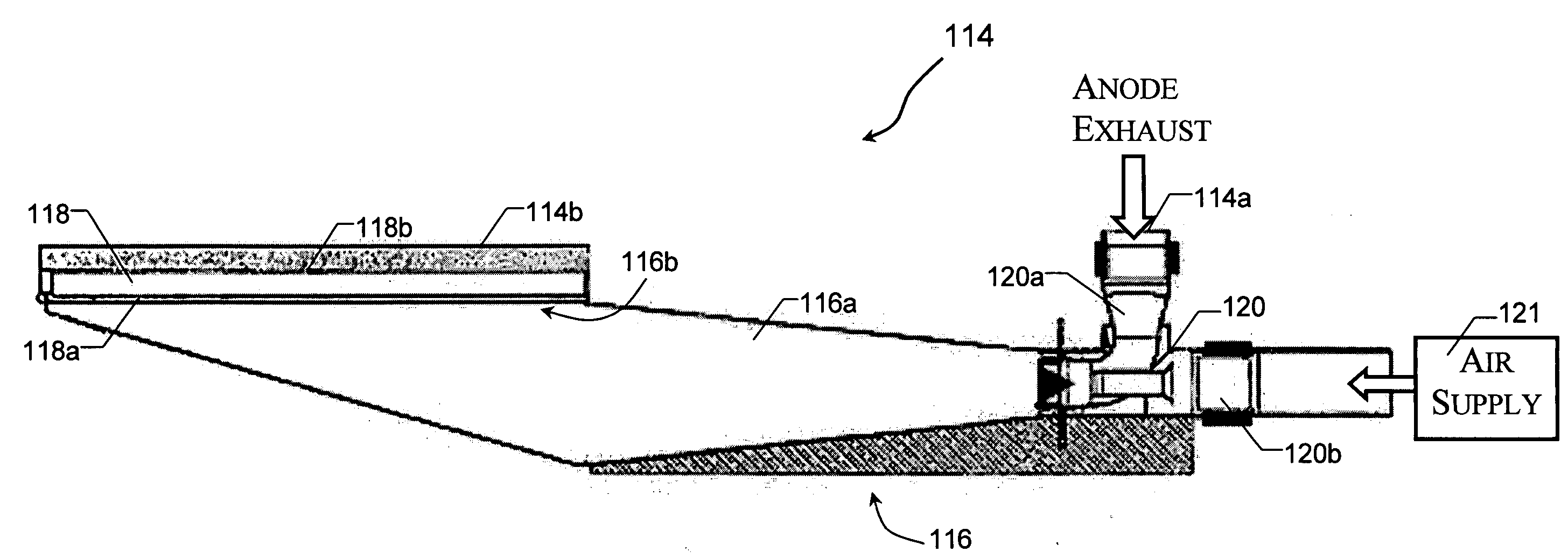
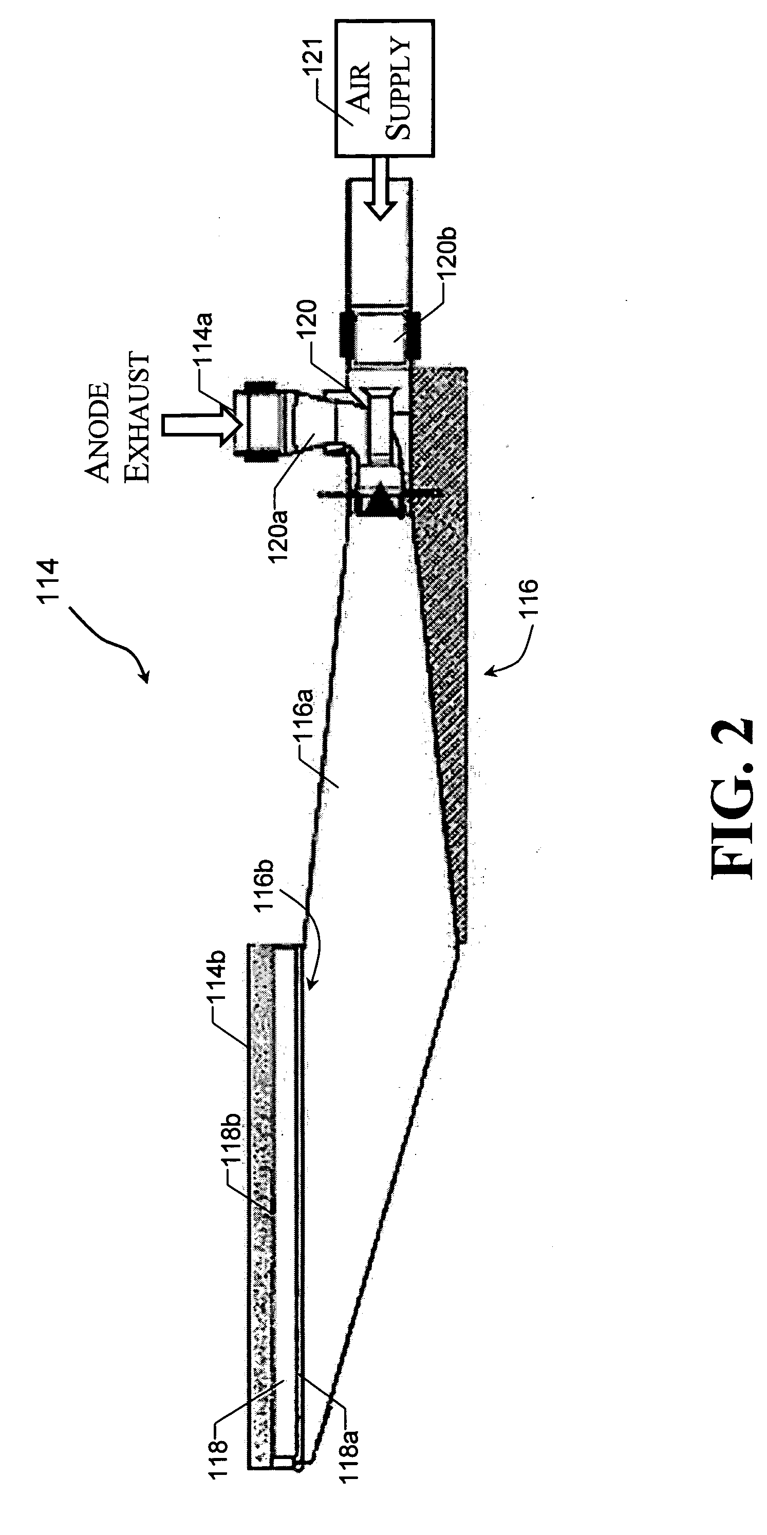
[0040] In the invention in which water is used as the solvent to remove electrolyte particulate deposits from the oxidizer unit 118, the oxidizer unit 118 and the system 100 are adapted or conditioned to pass a humidified gas at a predetermined temperature through the unit 118. A gas comprising air and water vapor is suitable for use as the humidified gas. In this case, the fuel cell system 100 is adapted to be at hot standby conditions or at low temperatures (about 500° F.) with no power generation mode during the removal of the electrolyte deposits.
[0041] More particularly, FIG. 5 shows the oxidizer assembly 114 of FIG. 2 modified to provide an inlet opening 130 in the mixer 116 coupled to a humidified gas supply 132. In this case, with the system 100 shutdown, humidified gas is supplied from the humidified gas supply 132 to the mixer 116 through the opening 130 by opening a valve 130a which controls the delivery of humidified gas to the assembly 114. Particularly, the valve 130a is
third embodiment
[0047] In accordance with the invention, the system 100 and oxidizer assembly 114 are adapted so that removing of electrolyte particulate deposits from the surface 118a of the oxidizer unit 118 is realized by combustion or heating. In this case, the fuel cell system 100 is adapted to be placed in a hot standby pre-ignition mode or state and no power is being produced by the system.
[0048] More particularly, the system 100 is operated in a hot standby pre-ignition mode to increase the temperature within the oxidizer assembly 114 to cause flaking and vaporization of the electrolyte particulate deposits on the oxidizer unit 118 without affecting the performance of the oxidizer catalyst. Particularly, the temperature is increased to approximately 790 to 840° Celsius. The desired temperature target will be achieved by adjusting the air and fuel ratio to favor combustion, resulting in higher temperatures at the surface of the catalyst. In this case, the maximum desired temperature during hot
fourth embodiment
[0053] In accordance with the invention, the system 100 and oxidizer assembly 114 are adapted or conditioned to remove electrolyte particulates in the anode exhaust and air mixture by entrapping the electrolyte particulates. More particularly, as shown in FIG. 7, a filter, depicted as a vane filter 134, is positioned within the mixing zone 116a of the mixer unit 116 of the assembly 114 to remove electrolyte particulates in the gas mixture passing therethrough. The filter 134 thus continuously removes electrolyte particulates, while the system 100 remains in operation with the the oxidizer unit retained in the assembly 114 and the assembly 100 retained in the system 100.
[0054] As shown in FIG. 7, the vane filter 134 is positioned in the mixing zone 116a so that the gas mixture is required to pass through the filter 134 before reaching the oxidizer unit 118. In this case, the vane filter 134 is perpendicular to the direction of the gas flow to allow direct impingement of the electrolyte
PUM
| Property | Measurement | Unit |
|---|---|---|
| Temperature | aaaaa | aaaaa |
| Temperature | aaaaa | aaaaa |
| Temperature | aaaaa | aaaaa |
Abstract
Description
Claims
Application Information
 - R&D Engineer
- R&D Manager
- IP Professional
- Industry Leading Data Capabilities
- Powerful AI technology
- Patent DNA Extraction
Browse by: Latest US Patents, China's latest patents, Technical Efficacy Thesaurus, Application Domain, Technology Topic.
© 2024 PatSnap. All rights reserved.Legal|Privacy policy|Modern Slavery Act Transparency Statement|Sitemap