Hammer drill with a mode changeover mechanism

a technology of changeover mechanism and hammer drill, which is applied in the direction of manufacturing tools, percussive tools, and machining tools, etc., can solve the problem of complex challenges

Active Publication Date: 2006-09-14
BLACK & DECKER INC
View PDF45 Cites 115 Cited by
  • Summary
  • Abstract
  • Description
  • Claims
  • Application Information

AI Technical Summary

Benefits of technology

The technical effect described this patented technology allows for different modes of operation when used on tools like handsaws or screwdrivers. It also prevents damage from excess torque caused during use due to slippage between parts.

Problems solved by technology

The technical problem addressed in this patented text relates how to improve the efficiency or effectiveness of an electronic device by reducing its size while still maintaining their ability for communication with other devices on it's own network (the internet).

Method used


Image

  • Hammer drill with a mode changeover mechanism
  • Hammer drill with a mode changeover mechanism
  • Hammer drill with a mode changeover mechanism

Examples


Embodiment Construction

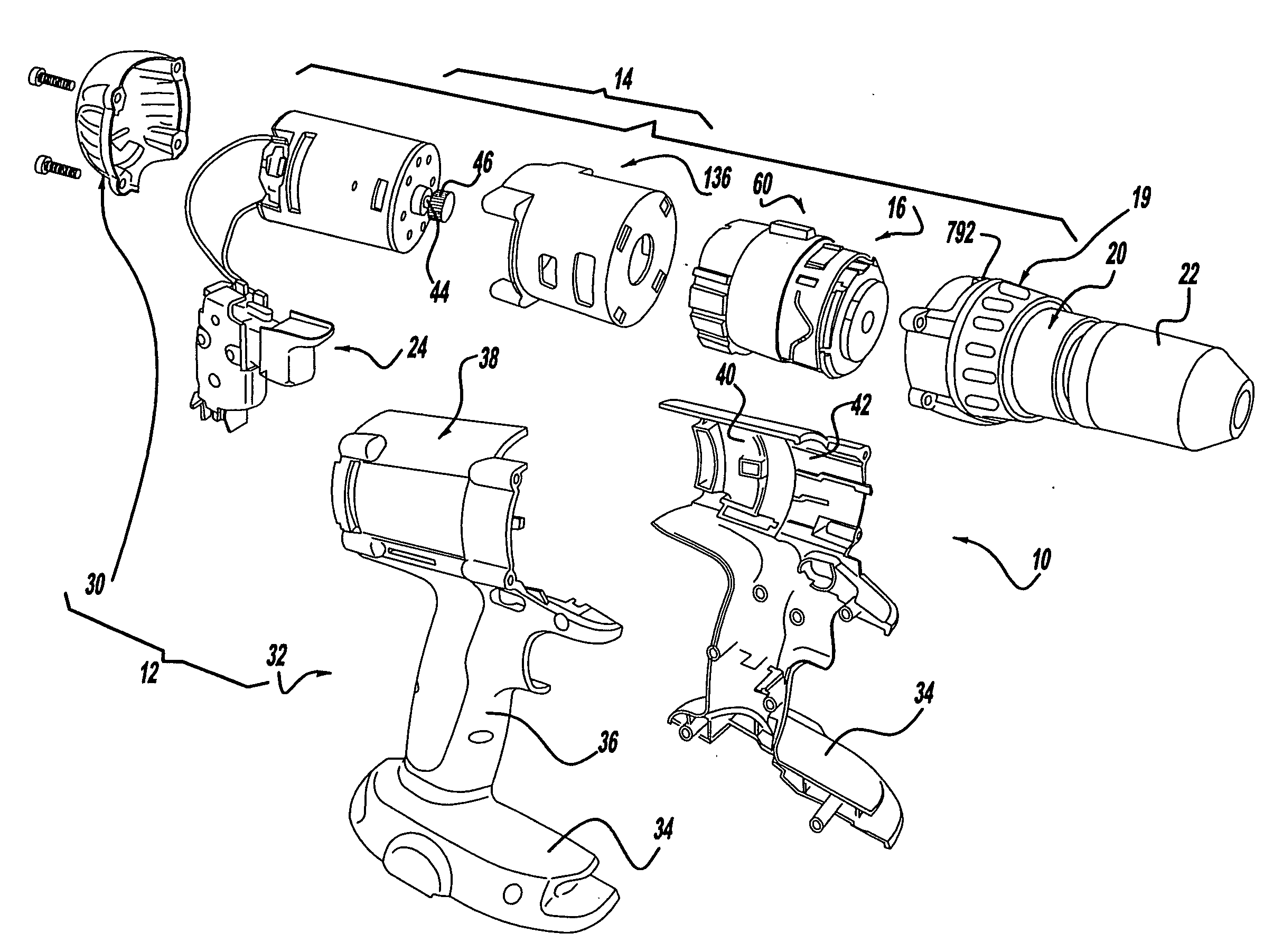
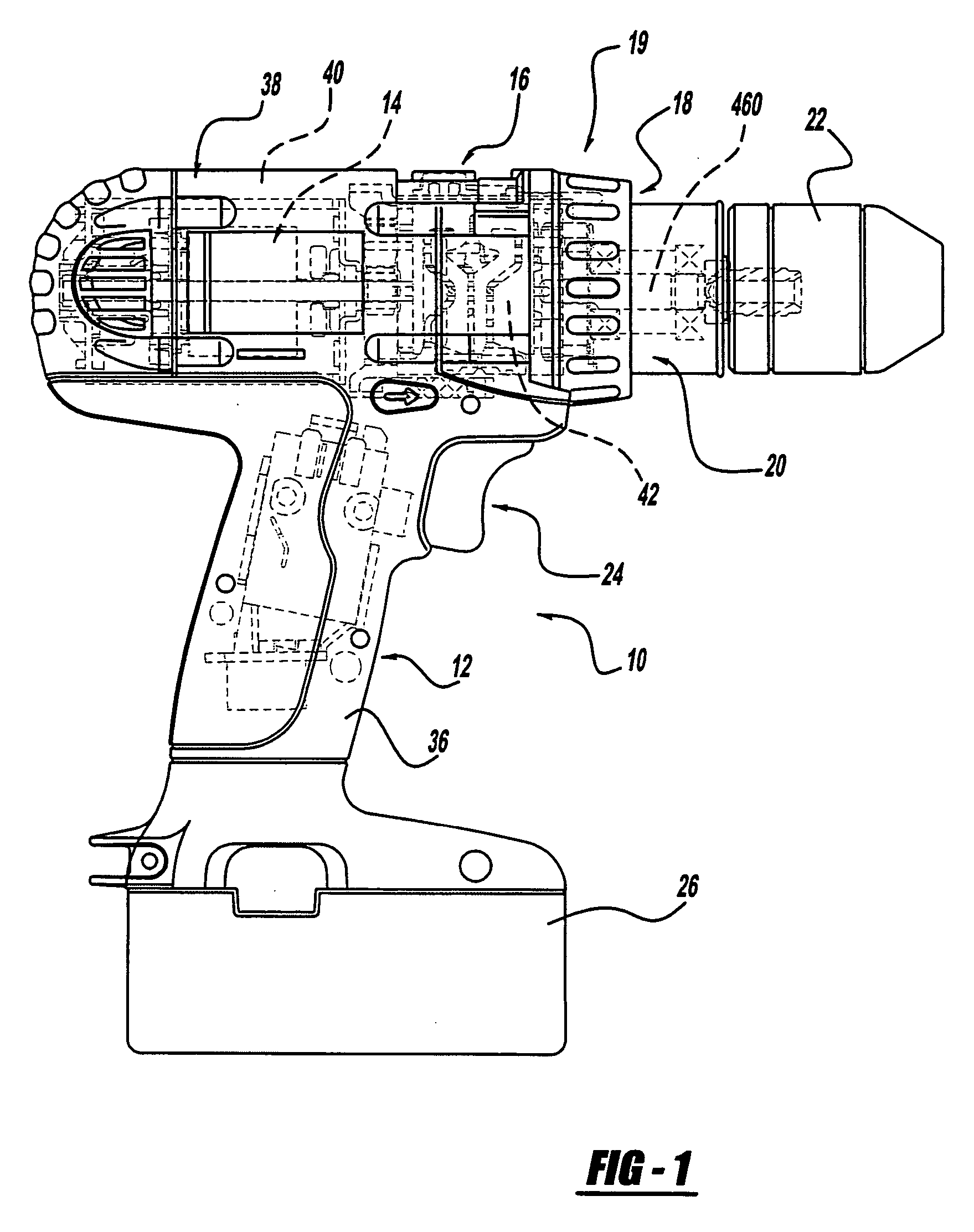
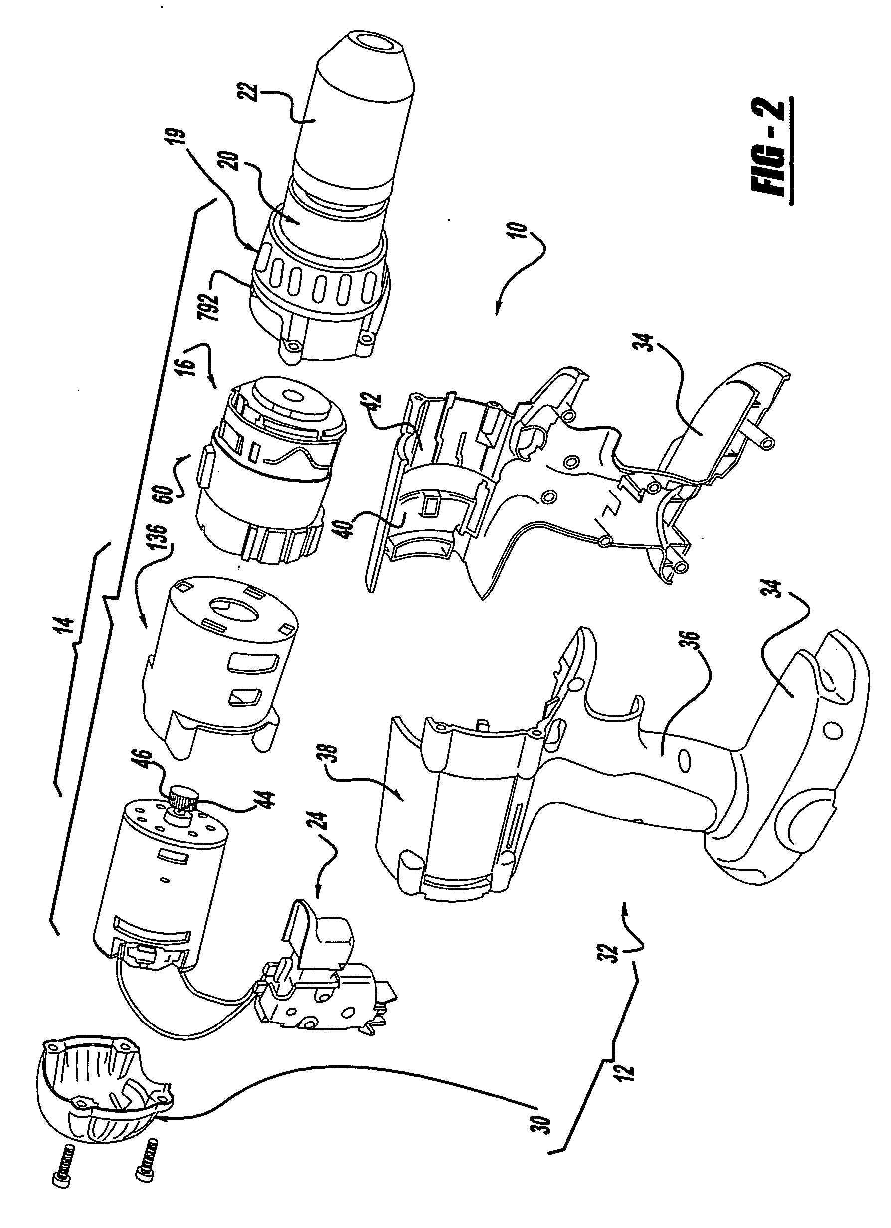
[0050] With reference to FIGS. 1 and 2 of the drawings, a hammer drill / driver constructed in accordance with the teachings of the present invention is generally indicated by reference numeral 10. As those skilled in the art will appreciate, the hammer drill driver 10 may be either a cord or cordless (battery operated) device and can have a housing 12, a motor assembly 14, a multi-speed transmission assembly 16, a clutch mechanism 18, a percussion or hammer mechanism 19, an output spindle assembly 20, a chuck 22, a trigger assembly 24 and a battery pack 26. Those skilled in the art will understand that several of the components of hammer drill / driver 10, such as the chuck 22, the trigger assembly 24 and the battery pack 26, are conventional in nature and need not be described in significant detail in this application.

[0051] Reference may be made to a variety of publications for a more complete understanding of the operation of the conventional features of hammer drill / driver 10.


PUM


Abstract

A hammer drill/driver with a motor having an output member, a planetary transmission, a clutch assembly and a clutch bypass. The planetary transmission, which includes a ring gear, receives rotary power from the output member and produces a rotary output. The clutch assembly has a clutch profile, which is coupled to the ring gear, and a first pin assembly having a first follower, a first pin member and a first spring that biases the first follower into contact with the clutch profile. The clutch bypass has a bypass profile, which is coupled to the ring gear, and second pin assembly having a second follower, a second pin member, a third spring, which biases the second follower away from the bypass profile, and a fourth spring, which biases the second follower away from the second pin member. A method for operation of a hammer drill/driver is also provided.

Description


Claims


Application Information

Patent Timeline
Owner BLACK & DECKER INC
Why Eureka
Try Eureka