Heat-Generating Element of a Heating Device

Inactive Publication Date: 2007-03-29
CATEM
View PDF6 Cites 18 Cited by
  • Summary
  • Abstract
  • Description
  • Claims
  • Application Information

AI Technical Summary

Benefits of technology

[0009] The object of the invention under consideration is to provide a heat-generating element of a heating device for heating air, as well as a corresponding heating dev

Problems solved by technology

Otherwise, the problem that arises is an increased transition resistance, which, particularly in the case of the use of the heat-generating elements in auxiliary heaters for motor vehicles, can lead to local overheating due to the high currents.
As a result of this thermal event, the heat-generating element can be damaged.
Furthermore, the PTC elements are self-regulating resistance heaters that emit a lower heat output at an increased temperature, so that local overheating can lead to a disturbance in the self-regulating characteristics of the PTC elements.
In addition, at high temperatures in the area of an auxiliary heater, vapours or gases can develop tha

Method used


Image

  • Heat-Generating Element of a Heating Device
  • Heat-Generating Element of a Heating Device
  • Heat-Generating Element of a Heating Device

Examples


Embodiment Construction

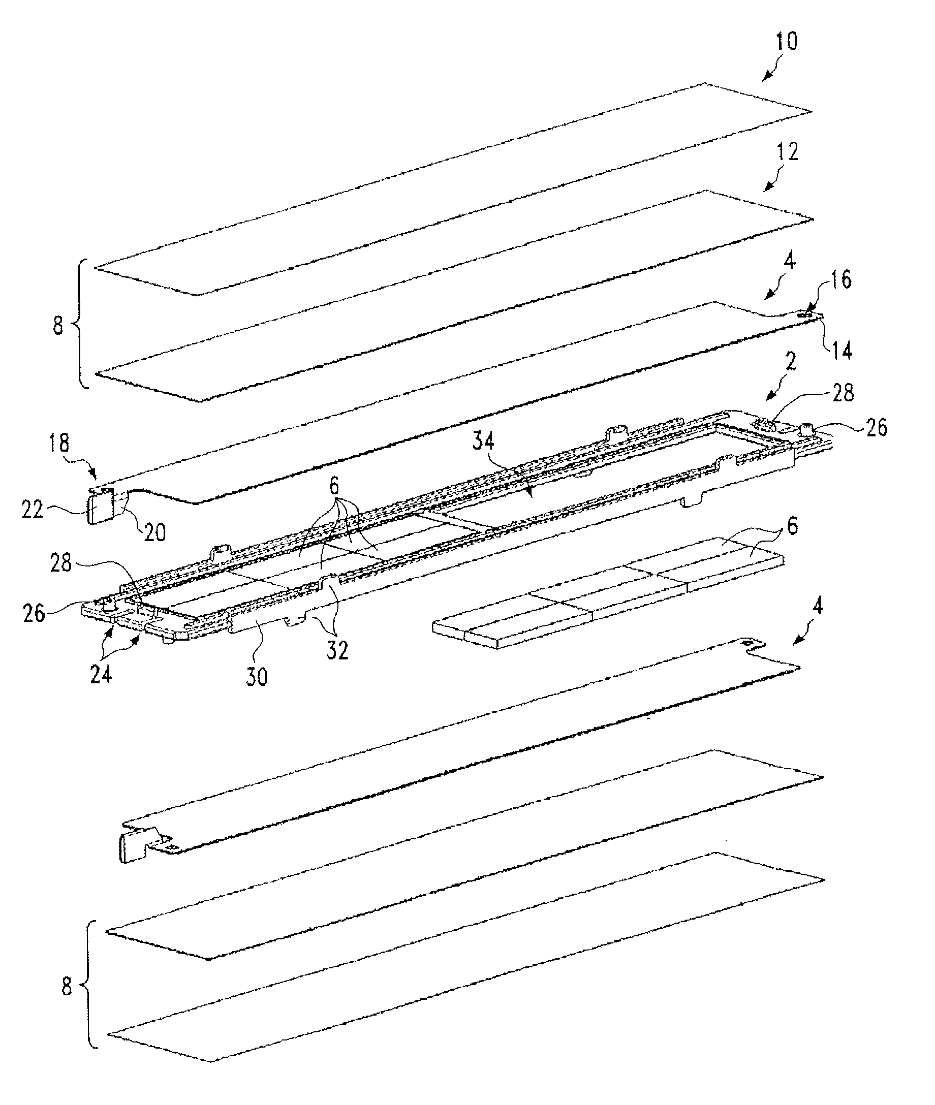
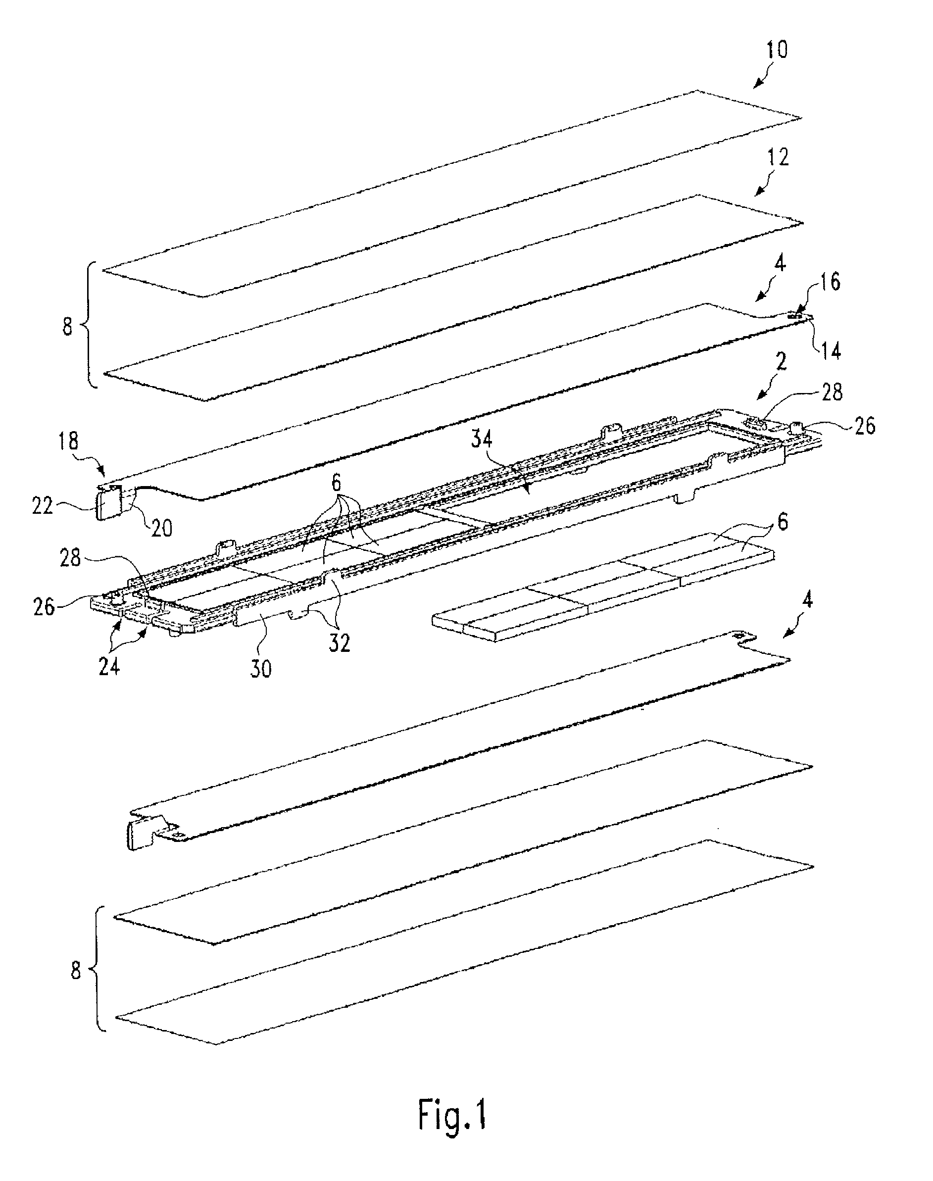
[0042]FIG. 1 shows a perspective side-view of the essential parts of an embodiment of a heat-generating element in a blown-up representation. The heat-generating element has a positioning frame 2, made of injection-moulded plastic, whose middle longitudinal axis forms a bisecting plane of the heat-generating element. This element is essentially formed with one side the mirror image of the other, and initially has contact plates 4 provided on each side of the positioning frame 2, said contact plates holding between them the PTC elements 6 held in the positioning frame 2. On the exterior side of the contact plates 4 is located a two-layer insulating layer 8, comprising an exterior insulating foil 10 and an inner ceramic plate 12, that fits directly against the contact plate 4. The ceramic plate 12 is a relatively thin aluminium oxide plate that provides very good electric dielectric strength of roughly 28 kV / mm and good thermal conductivity of more than 24 W / (m K). The plastic foil 1


PUM


Abstract

A heat-generating element of a heating device for heating air includes at least one PTC element and, lying on opposing side surfaces of the PTC element, electric strip conductors. A heat-generating element that is improved with respect to the safety against electric flashovers is created with the invention under consideration by means of surrounding the two electric strip conductors on the outside by a non-conductive insulating layer. A heating device for heating air with multiple heat-generating elements is also disclosed with each heating element including at least one PTC element and, lying on opposing side surfaces of the PTC element, electric strip conductors and multiple heat-emitting elements that are arranged in parallel layers and that are held in position lying on opposing sides of the heat-generating element. The heat-emitting elements are essentially potential-free and protected against electric flashovers with a higher degree of certainty due to the fact that the heat-emitting elements lie on opposing sides of the heat-generating element, with an insulating layer placed in between.

Description


Claims


Application Information

Patent Timeline
Owner CATEM
Why Eureka
Try Eureka