Photomultiplier

Inactive Publication Date: 2007-10-18
HAMAMATSU PHOTONICS KK
View PDF19 Cites 3 Cited by
  • Summary
  • Abstract
  • Description
  • Claims
  • Application Information

AI Technical Summary

Benefits of technology

[0008]The inventors have studied conventional multichannel photomultipliers in detail, and as a result, have found problems as follows. Namely, in each of the conventional multichannel photomultipliers, because electron multiplications are performed by electron multiplier channels that are assigned in advance according to photoelectron emission positions of the photocathode, the positions of the respective electrodes are des

Problems solved by technology

The inventors have studied conventional multichannel photomultipliers in detail, and as a result, have found problems as follows.
However, in such multichannel photomultipliers, no improvements had

Method used


Image

  • Photomultiplier
  • Photomultiplier
  • Photomultiplier

Examples


Embodiment Construction

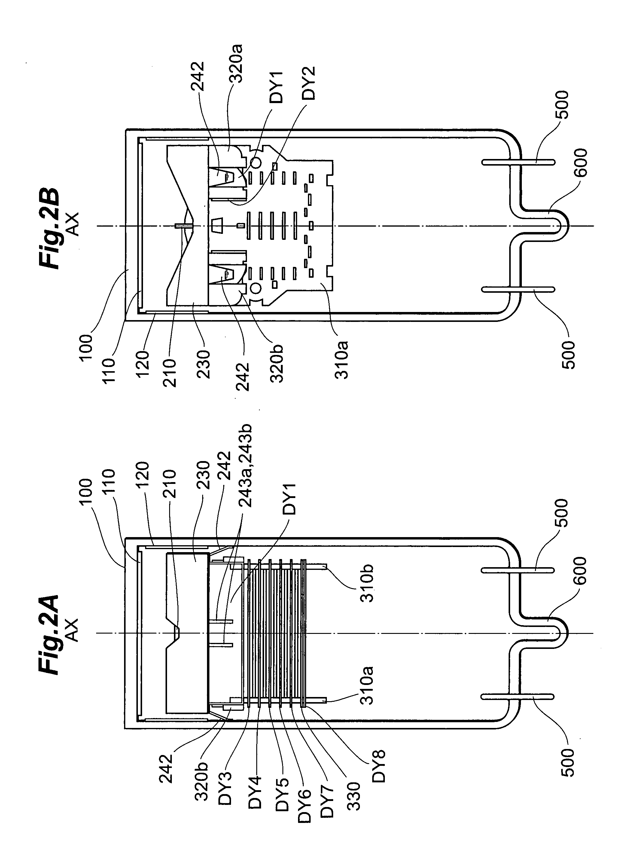
[0034]In the following, embodiments of a photomultiplier according to the present invention will be explained in detail with reference to FIGS. 1, 2A, 2B, 3, 4A-5C, 6-10, and 11A-14B. In the explanation of the drawings, constituents identical to each other will be referred to with numerals identical to each other without repeating their overlapping descriptions.

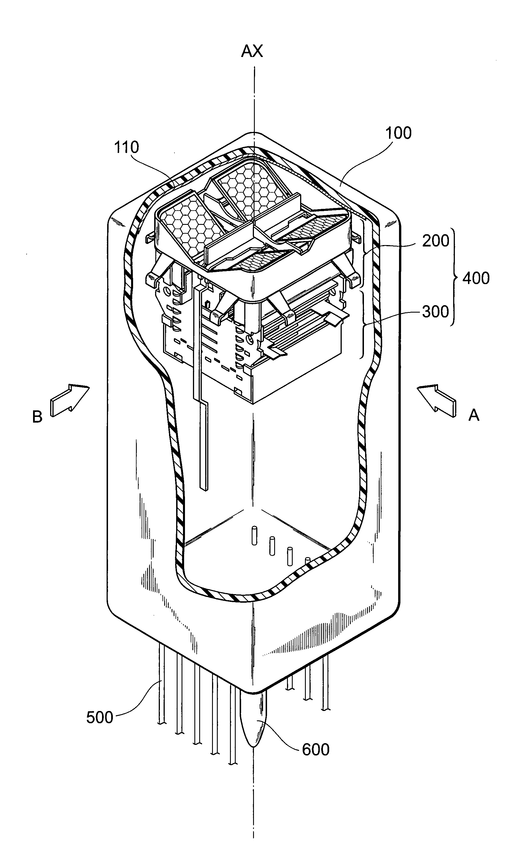
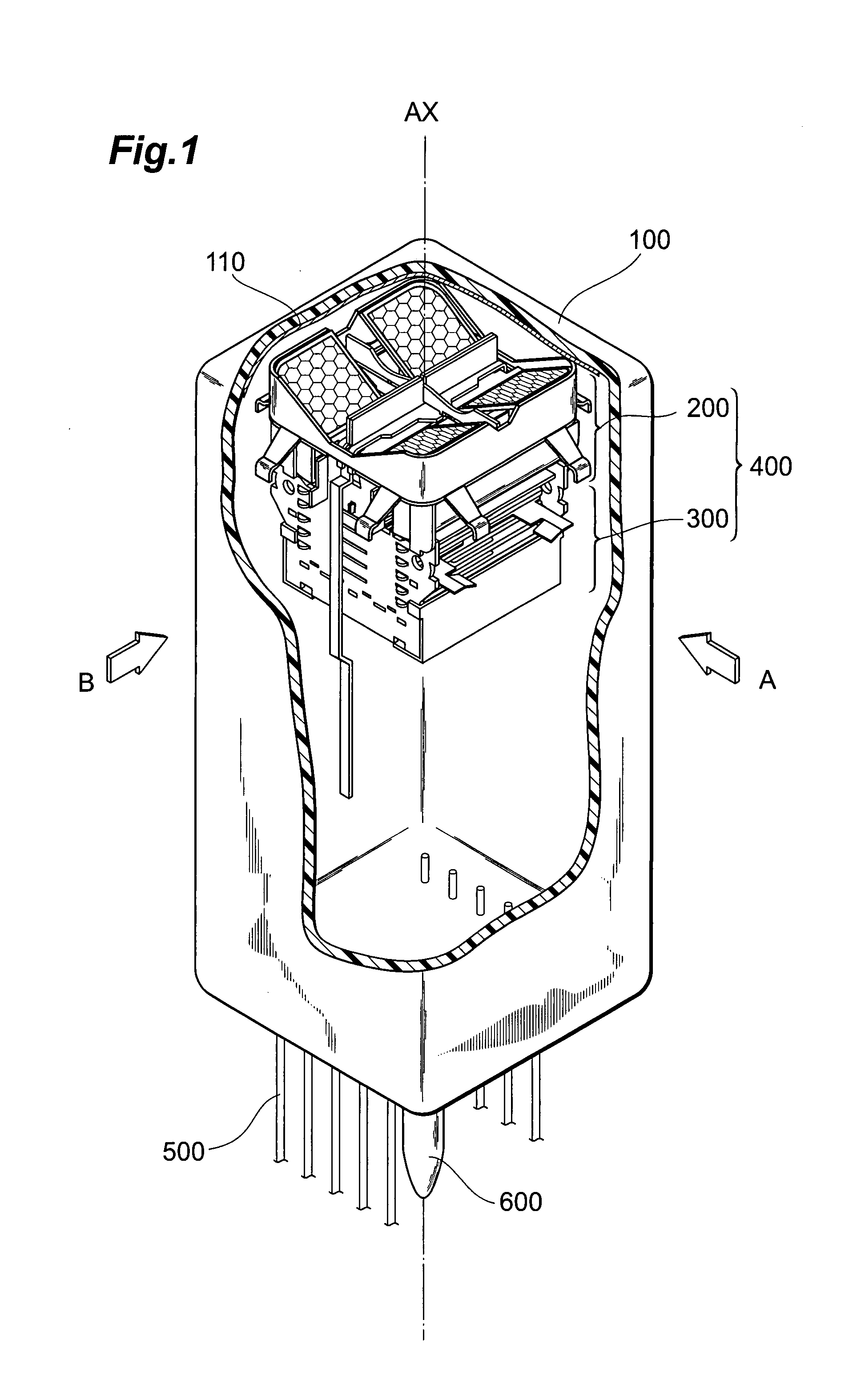
[0035]FIG. 1 is a partially cutaway view of a schematic configuration of an embodiment of a photomultiplier according to the present invention.

[0036]As shown in FIG. 1, the photomultiplier according to the present invention comprises a sealed container 100, with a pipe 600, which is used to depressurize the interior to a predetermined degree of vacuum (and the interior of which is filled after vacuum drawing), provided at a bottom portion, and comprises a photocathode 110 and an electron multiplier section 400 which are provided inside the sealed container 100.

[0037]The sealed container 100 is constituted by a cylindrical bulb,


PUM


Abstract

The present invention relates to a photomultiplier having a configuration for improving response time characteristics. The photomultiplier comprises at least a sealed container, a photocathode, and an electron multiplier section. The electron multiplier section has an upper unit and a lower unit. The upper unit includes a focusing electrode, a mesh electrode, and a first dynode. The lower unit includes the subsequent dynodes excluding the first dynode and a pair of insulating supporting members. The length in the longitudinal direction of the first dynode is made greater than the interval between the pair of insulating supporting members. By this configuration, the sizes of the effective regions of the assigned electron multiplier channels can be set arbitrarily without being restricted by the pair of insulating supporting members.

Description


Claims


Application Information

Patent Timeline
Owner HAMAMATSU PHOTONICS KK
Why Eureka
Try Eureka