Integrated Circuit Chip With Repeater Flops and Method for Automated Design of Same

a repeater flop and integrated circuit technology, applied in logic circuit coupling/interface arrangement, pulse technique, instruments, etc., can solve the problems of repeater flops not being associated with just any signal wires, many complications, etc., to overcome the distance limitation and influence the design

Inactive Publication Date: 2008-03-13
ADVANCED MICRO DEVICES INC
View PDF12 Cites 5 Cited by
  • Summary
  • Abstract
  • Description
  • Claims
  • Application Information

AI Technical Summary

Benefits of technology

The technical effect of this patented technology is improved efficiency when implementing repetitive circuit techniques like repeating buffers. By breaking up the signal paths through multiple stages instead of sending them all at once, fewer delays occur during transmission compared to traditional methods. However, there still exist issues related to placing these repeater locks accurately due to their size limitations. To address those problems, the inventors propose introducing a method called Repair Factor Flooding (RF), which allows for efficient allocation and inserting repeater blocks without adding extra delay time. Overall, this innovation improves performance while reducing complexity.

Problems solved by technology

This technical problem addressed in this patented text relates to improving the efficiency of repeating connections within electronic chips while reducing their size without sacrificing quality. Current methods involve cramming multiple layers down onto another plane called a "wafer," but these techniques require expensive equipment like lasers or electron beam writers. Therefore, new solutions would improve performance and reduce costs.

Method used


Image

  • Integrated Circuit Chip With Repeater Flops and Method for Automated Design of Same
  • Integrated Circuit Chip With Repeater Flops and Method for Automated Design of Same
  • Integrated Circuit Chip With Repeater Flops and Method for Automated Design of Same

Examples


Embodiment Construction

[0028] The following detailed description of the present invention refers to the accompanying drawings that illustrate exemplary embodiments consistent with this invention. Other embodiments are possible, and modifications may be made to the embodiments within the spirit and scope of the invention. Therefore, the detailed description is not meant to limit the invention. Rather, the scope of the invention is defined by the appended claims.

[0029] It would be apparent to one of skill in the art that the present invention, as described below, may be implemented in many different embodiments of software, hardware, firmware, and / or the entities illustrated in the figures. Any actual software code with the specialized control of hardware to implement the present invention is not limiting of the present invention. Thus, the operational behavior of the present invention will be described with the understanding that modifications and variations of the embodiments are possible, given the level


PUM


Abstract

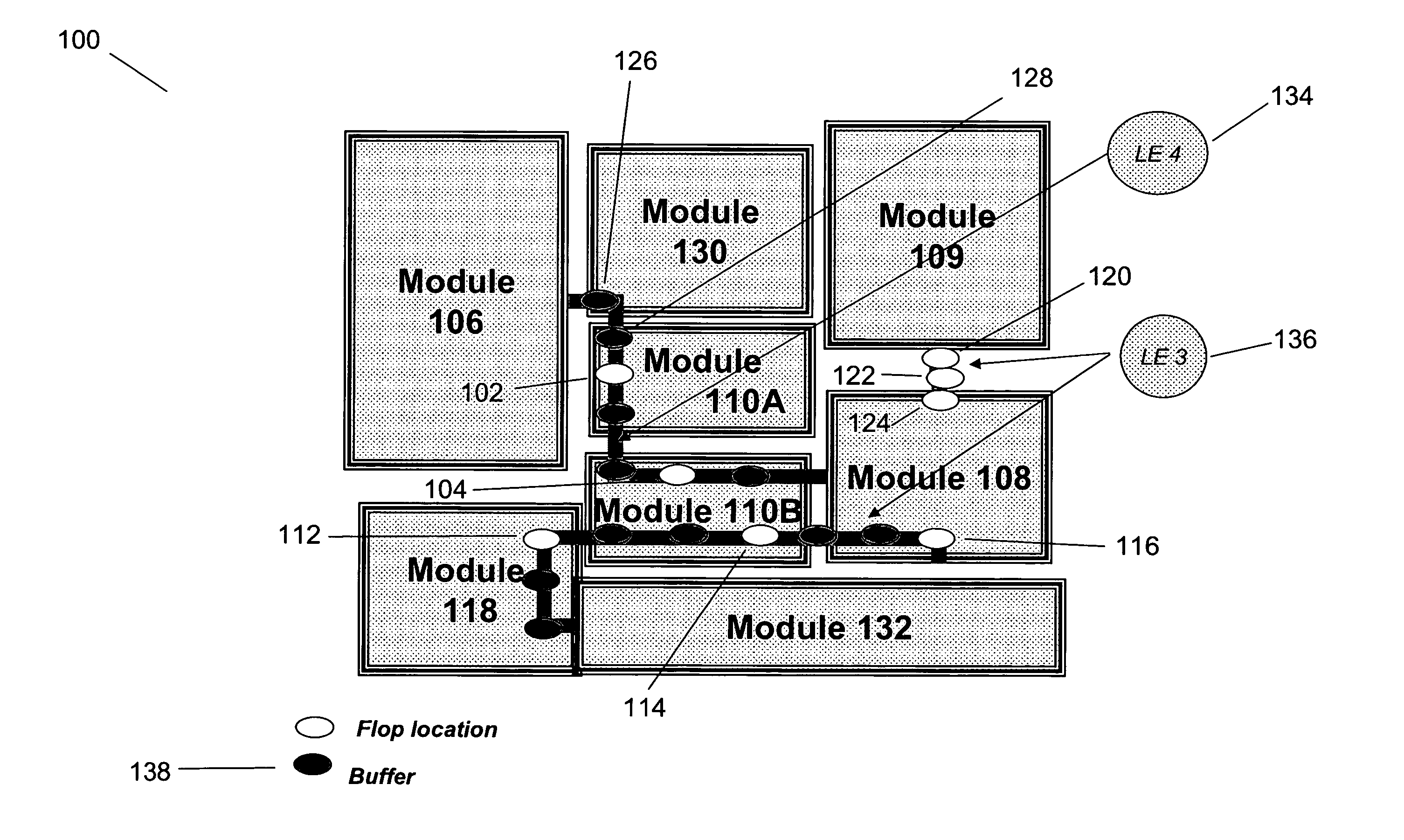
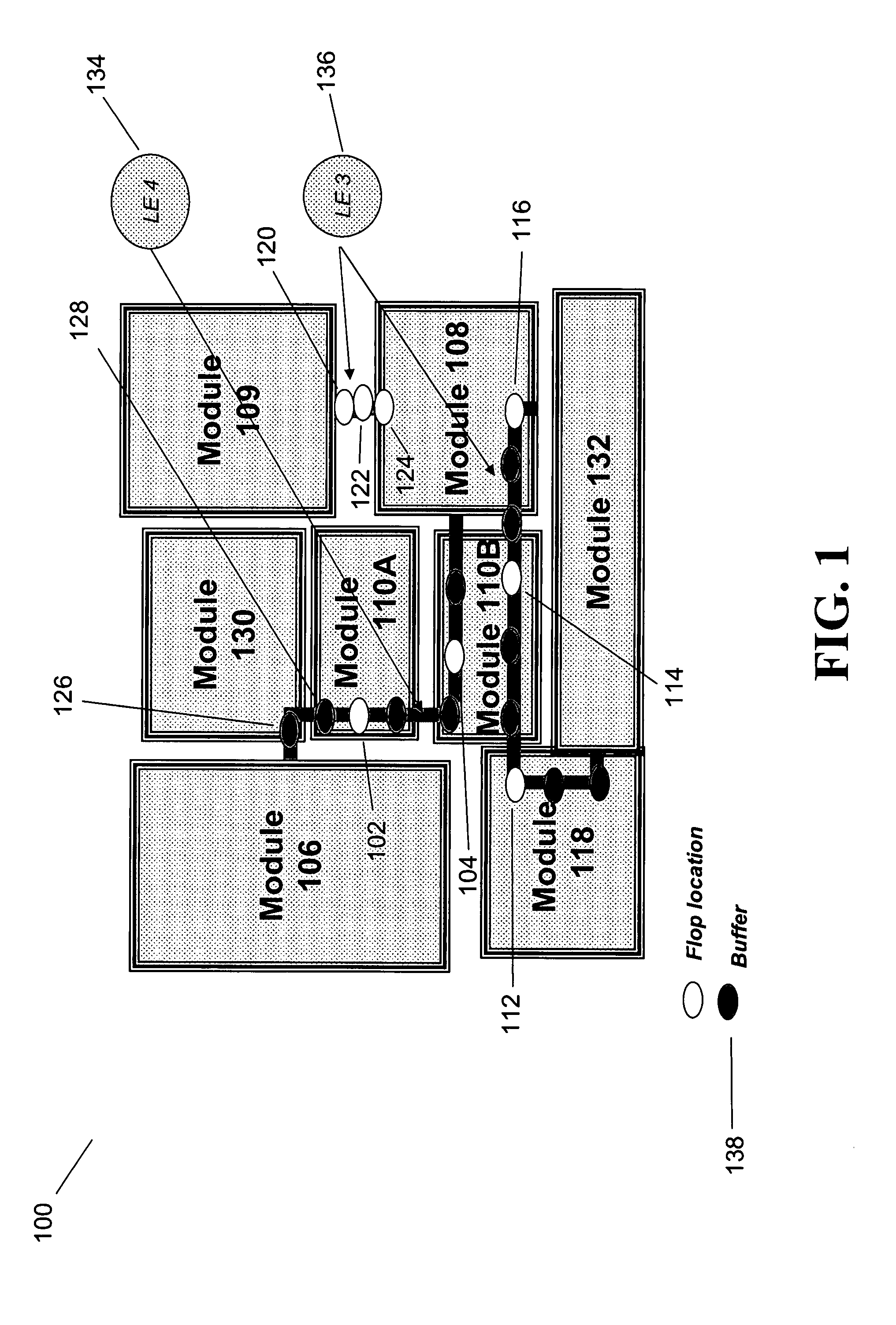
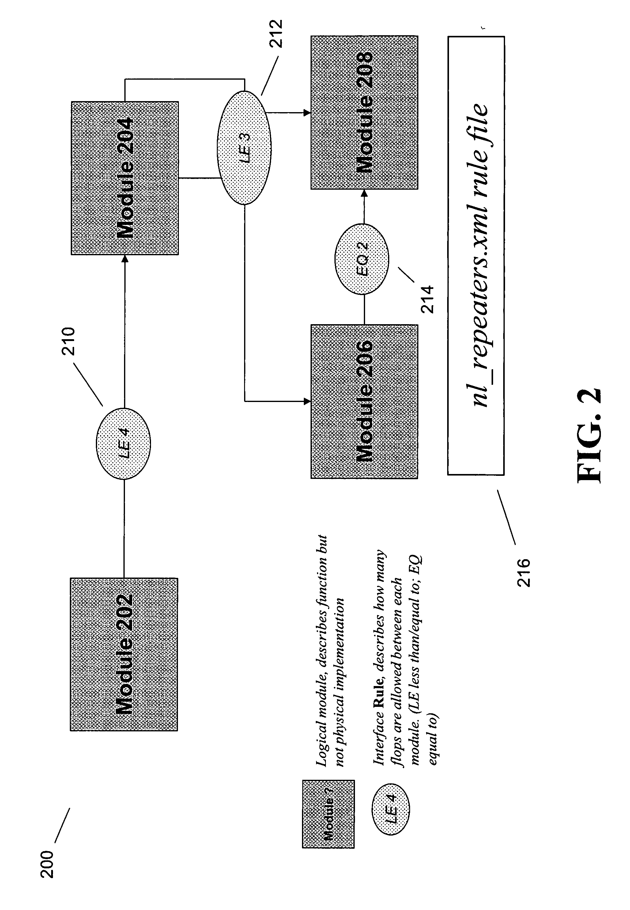
An integrated circuit (IC) chip having repeaters for propagating signals along relatively long wires that extend between and among lower-level physical blocks of the IC chip, wherein the repeaters are implemented as clocked flip-flops (or “repeater flops”). A method for automatically inserting and allocating such repeater flops during the logical and physical design of the IC chip is also provided.

Description


Claims


Application Information

Patent Timeline
Owner ADVANCED MICRO DEVICES INC
Why Eureka
Try Eureka