Flex-fuel variable displacement engine control system and method

a variable-distance engine and control system technology, applied in the direction of electric control, machines/engines, instruments, etc., can solve the problems of limited vde operation window, possible modest fuel economy gains, and limited potential fuel economy gains, so as to improve performance, extend vde operation, and expand vde operation.

Inactive Publication Date: 2008-05-22
FORD GLOBAL TECH LLC
View PDF12 Cites 21 Cited by
  • Summary
  • Abstract
  • Description
  • Claims
  • Application Information

AI Technical Summary

Benefits of technology

The technical problem discussed for these types of engines relates to improving their ability to handle different fuels while maintaining good efficiency. This includes ensuring that all parts are working properly together without causing damage from excessive heat buildup caused by misfire events. Additionally, it focuses on optimising airflow through the engine's intake manifold, which helps reduce noise pollution.

Problems solved by technology

The technical problem addressed in this patented solution relates how to improve the efficiency or effectiveness of an electronic device by improving its performance without adding extra components that may be detrimental for it's overall functioning.

Method used


Image

  • Flex-fuel variable displacement engine control system and method
  • Flex-fuel variable displacement engine control system and method
  • Flex-fuel variable displacement engine control system and method

Examples


Embodiment Construction

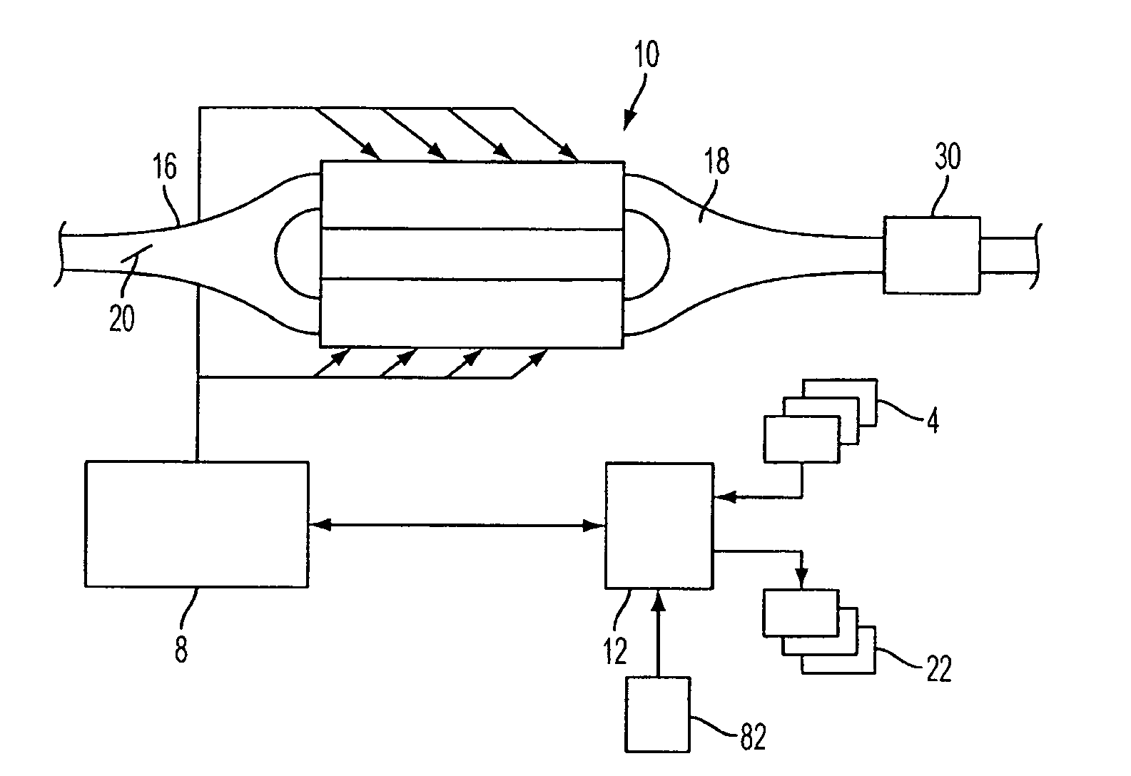
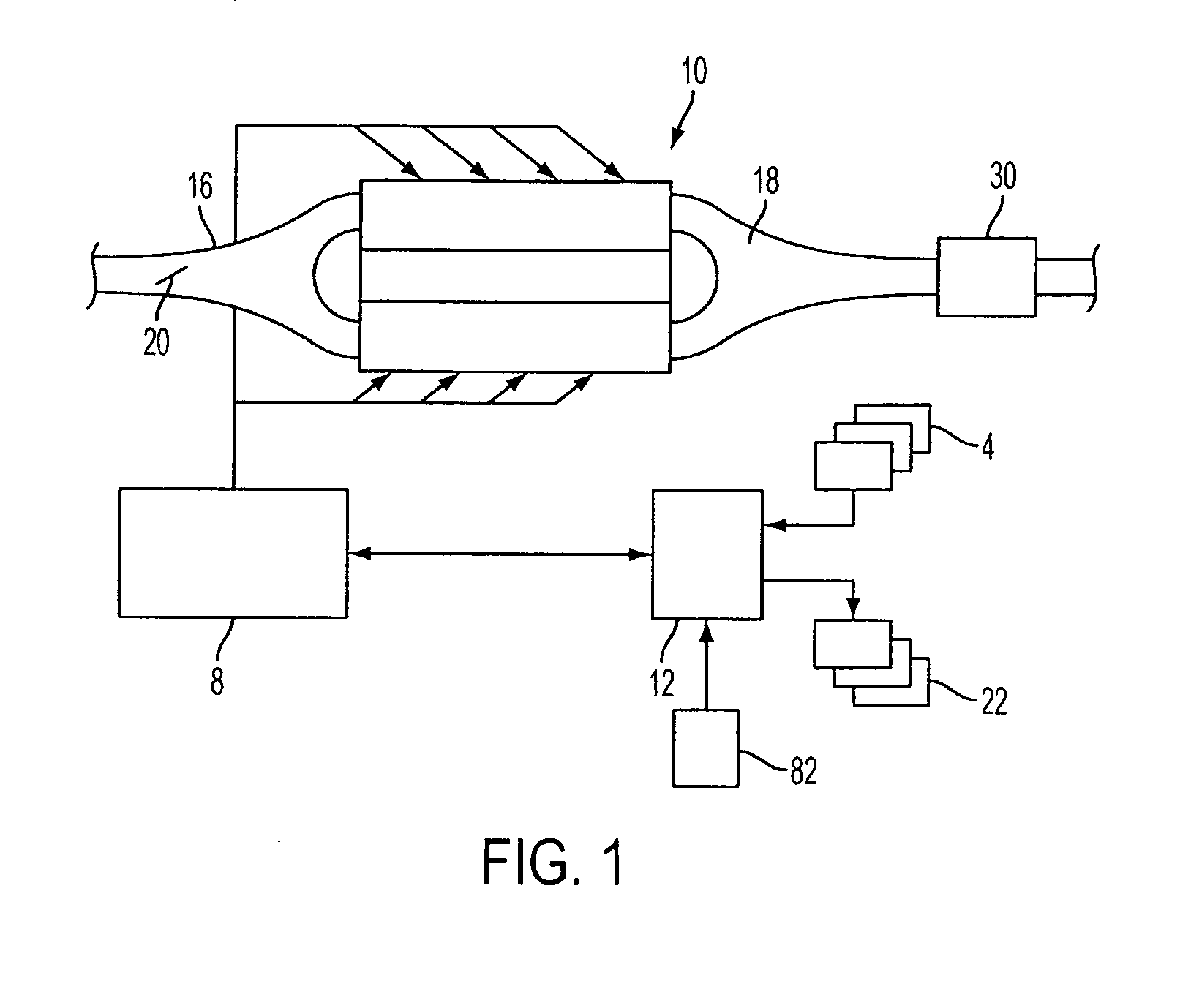
[0013]FIG. 1 shows an example variable displacement engine (VDE) 10, in which four cylinders (e.g., two in each bank) may have cylinder valves held closed during one or more engine cycles. The cylinder valves may be deactivated via hydraulically actuated lifters coupled to valve pushrods, or via a cam profile switching mechanism in which a cam lobe with no lift is used for deactivated valves. Still other valve deactivation mechanisms may also be used, such as electrically actuated valves.

[0014]Engine 10 may operate on a plurality of substances, which may be delivered via fuel system 8. Fuel system 8 may include various tanks, alcohol separator units, control and / or mixing valves, and injectors as described in more detail herein. Specifically, the various substances in fuel system 8 may include multiple different fuel blends, injection locations, or various other alternatives. In one example, multiple different substances having different gasoline and / or alcohol and / or water conce


PUM


Abstract

A method for operating an engine having at least one cylinder that may be deactivated and a fuel system operating with an alcohol fuel blend, comprising of adjusting a range of operating parameters in which the at least one cylinder is deactivated, where said range is adjusted as the alcohol blend of the fuel varies.

Description


Claims


Application Information

Patent Timeline
Owner FORD GLOBAL TECH LLC
Why Eureka
Try Eureka