Probe assembly, method of producing it and electrical connecting apparatus

a technology of electrical connection and assembly method, which is applied in the manufacture of contact parts, instruments, printed circuits, etc., can solve the problems of difficult adjustment to make such numerous probes, complicated work of adjusting to make all the probe tips contact properly with each corresponding electrical connection terminal of the device under test, and difficulty in making such numerous probes. , to achieve the effect of convenient production, efficient electrical testing and easy formation

Active Publication Date: 2009-03-05
NIHON MICRONICS
View PDF4 Cites 17 Cited by
  • Summary
  • Abstract
  • Description
  • Claims
  • Application Information

AI Technical Summary

Benefits of technology

The inventors have developed a new type of testing system called Prober Assembly (PGA). This allows multiple tiny electronic devices or components to be tested simultaneously by pressing them together at one point instead of individually attaching it onto other points. By keeping these small parts stable during measurement, efficiency gains may occur over traditional methods like manual labor-based tests. Additionally, this PGA design simplifies the process of changing connections from different types of connectors used within the systems' chassis. Overall, this technology improves overall performance and reliability of electronics manufacturing processes while reducing costs associated therewith

Problems solved by technology

In traditional methods for manufacturing electronic connectors used to measure voltage levels between different components within devices being tested, when one component needs more than just two connections while another connection only works correctly due to any distortion caused during installation. However, these techniques require manual intervention and involve complex procedures involving trial and error processes before final product quality ensures proper performance over its entire range of use conditions.

Method used


Image

  • Probe assembly, method of producing it and electrical connecting apparatus
  • Probe assembly, method of producing it and electrical connecting apparatus
  • Probe assembly, method of producing it and electrical connecting apparatus

Examples


Embodiment Construction

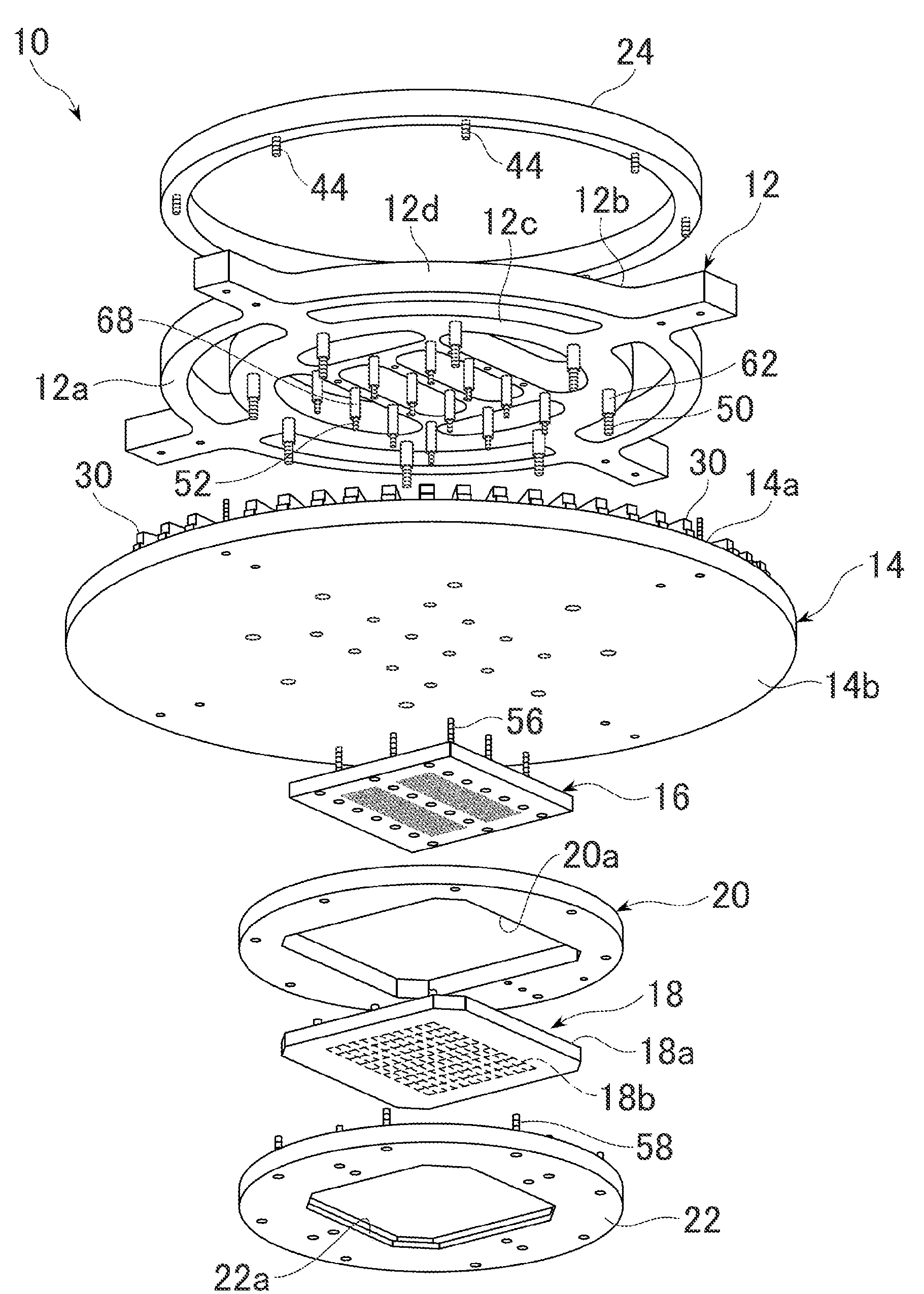
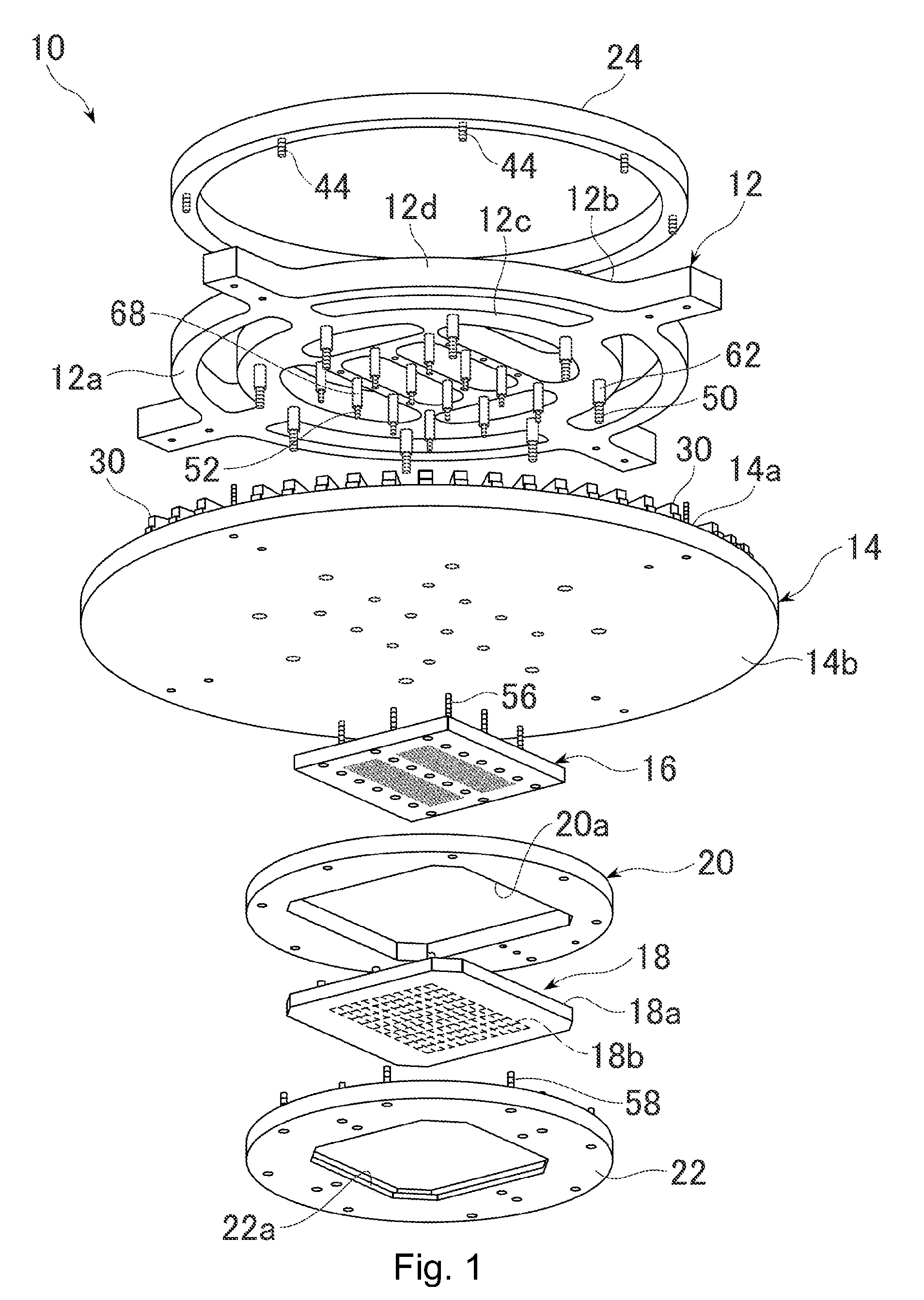
[0066]The electrical connecting apparatus 10 according to the present invention is shown in FIG. 1 in an exploded state. This electrical connecting apparatus 10 comprises: a flat plate-like supporting member 12, the underside 12a of which becomes a flat mounting reference plane; a circular flat plate-like wiring base plate 14 held by the mounting plane 12a of the supporting member; a probe assembly 18 electrically connected with the wiring base plate 14 through an electrical connector 16; a base ring 20 with a central opening 20a formed for receiving the electrical connector 16; and a securing ring 22 for sandwiching the edge portion of the probe assembly 18 in cooperation with the edge portion of the central opening 20a of the base ring. This securing ring 22 has in its central portion a central opening 22a permitting probes 18b mentioned later of the probe assembly 18 to be exposed. In the illustration, a thermal deformation inhibitor 24 for restraining a thermal deformation of the s


PUM

PropertyMeasurementUnit
Thicknessaaaaaaaaaa
Lengthaaaaaaaaaa
Adhesion strengthaaaaaaaaaa

Abstract

A probe assembly for use in electrical measurement of a device under test. The probe assembly comprises a plate-like probe base plate with bending deformation produced in a free state without load, and a plurality of probes formed on one face of the probe base plate to project from the face. All the tips of the probes are positioned on the same plane parallel to an imaginary reference plane of the probe base plate.

Description


Claims


Application Information

Patent Timeline
Owner NIHON MICRONICS
Why Eureka
Try Eureka