Uninterruptible Power Supply
- Summary
- Abstract
- Description
- Claims
- Application Information
AI Technical Summary
Benefits of technology
Problems solved by technology
Method used
Image

Examples
first exemplary embodiment
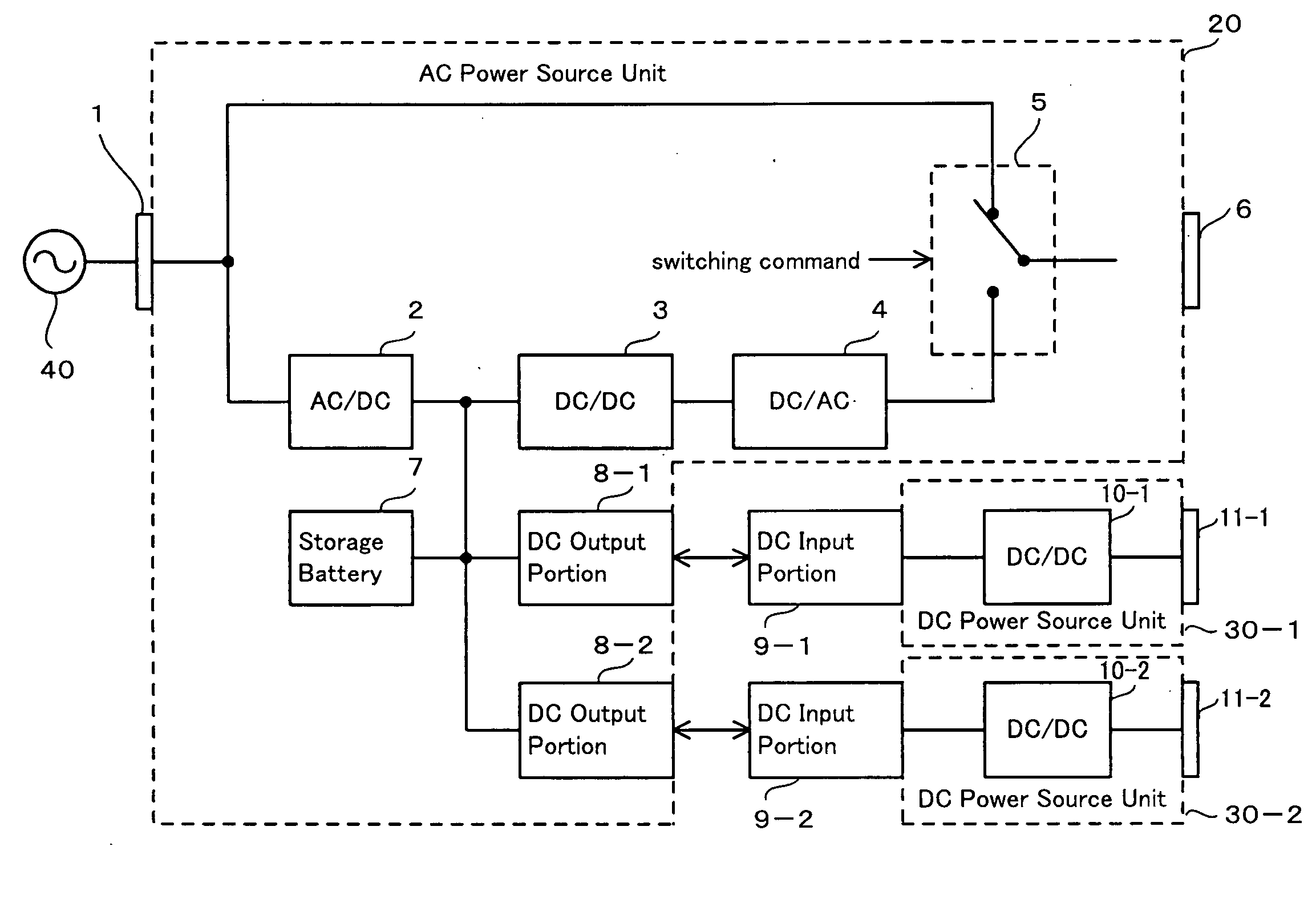
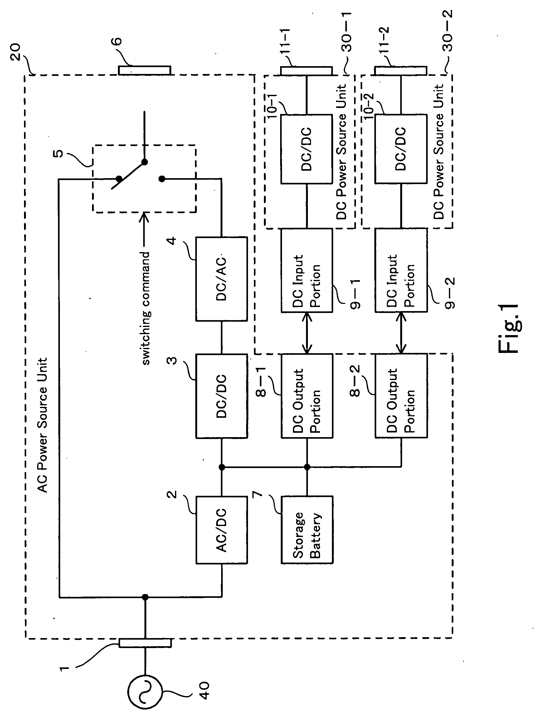
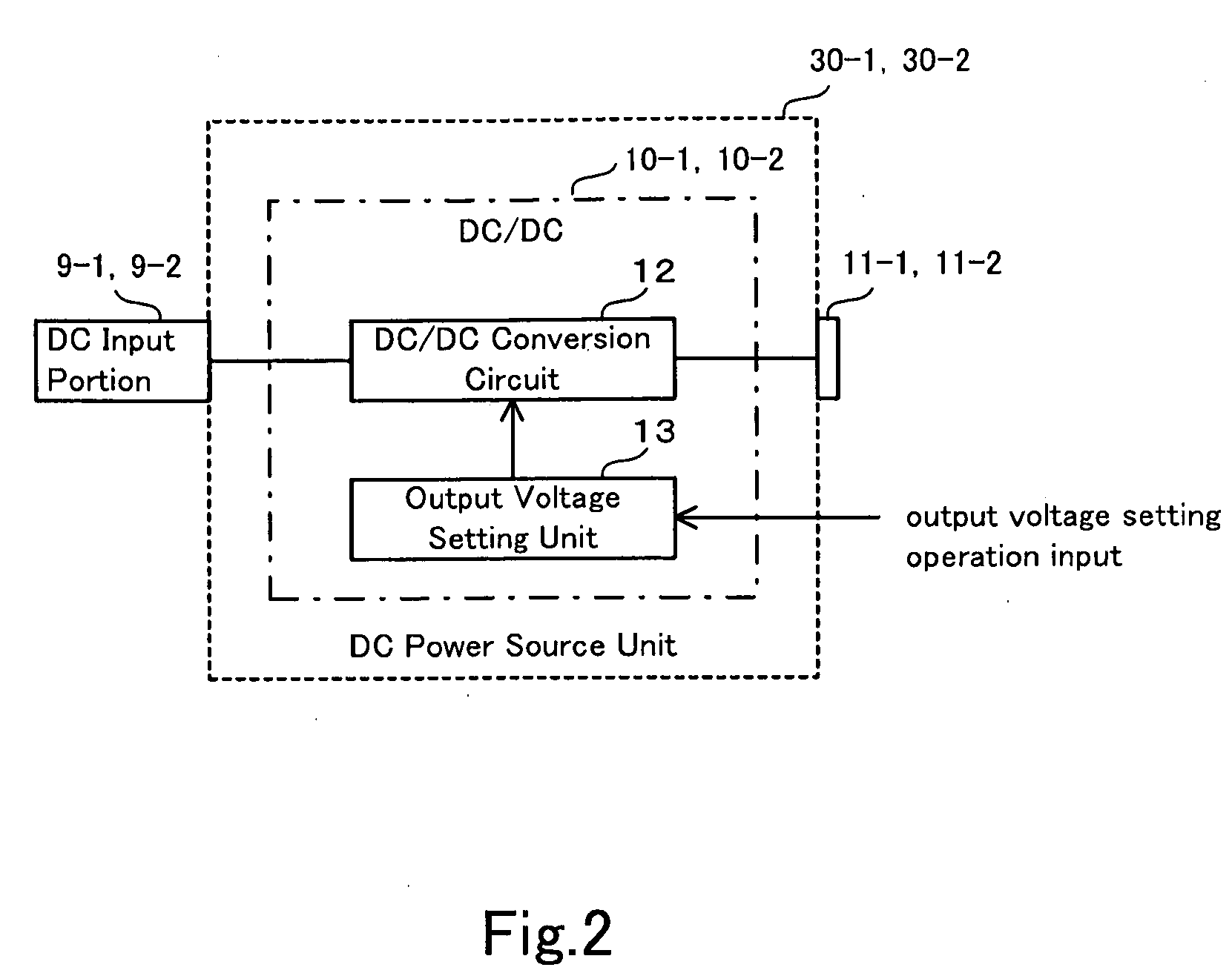
[0024]UPS in a first exemplary embodiment will be explained with referring to FIG. 1 and FIG. 2. FIG. 1 is a schematic view of UPS in the first exemplary embodiment. FIG. 2 is a structural view of a DC power source unit in UPS of the first exemplary embodiment.
[0025]UPS of the first exemplary embodiment comprises an AC power source unit 20, a DC power source unit 30-1 and a DC power source unit 30-2. The DC power source unit 30-1 and the DC power source unit 30-2 are placed in a container different from other container containing the AC power source unit 20. The AC power source unit 20, the DC power source unit 30-1 and the DC power source unit 30-2 are formed as detachable.
[0026]Namely, according to UPS of the exemplary embodiment, an AC input unit 1 is connected to an AC power source unit 40. An AC current of the AC power source unit 40 is converted to a DC current by an AC / DC converter 2 and stored in a storage battery 7 at normal time (non power interruption.) Further, when perfo
second exemplary embodiment
[0032]UPS in the second exemplary embodiment will be explained with referring to FIG. 3 and FIG. 4. FIG. 3 is a schematic view of UPS in the second exemplary embodiment. FIG. 4 is a structural view of a DC power source unit in UPS of the second exemplary embodiment. Here, the same numerical references are applied to the same constituents in the first exemplary embodiments.
[0033]In the first exemplary embodiment, DC power source units 30-1 and 30-2 output the DC current by using the DC current in the storage battery 7. On the other hand, in the second exemplary embodiment, DC power source units 31-1 and 31-2 output a DC current by using an AC current output by the AC output unit 6. Namely, the AC current, branched between the switching unit 5 and the AC output unit 6, is output to the AC output portions 14-1 and 14-2.
[0034]AC input units 15-1 and 15-2 of DC power source units 31-1 and 31-2 are detachably connected to AC output portions 14-1 and 14-2 of the AC power source unit 21. Depen
third exemplary embodiment
[0037]The third exemplary embodiment will be explained, with referring to FIG. 5 and FIG. 6. FIG. 5 is a schematic view of the third exemplary embodiment. FIG. 6 is a structural view of a DC power source unit in the third exemplary embodiment.
[0038]In first and second exemplary embodiments, the output voltage setting unit 13 is placed and a user sets a desirable output voltage value to DC power source units 30-1, 30-2, 31-1 and 31-2 by inputting the output voltage operation. But, in the third exemplary embodiment, other control function (or a controller) instead of the output voltage setting unit 13 is placed, making it possible for a user to perform desirable setting more than set the output voltage value to an arbitrary value.
[0039]For example, as shown in FIG. 5, a power interruption message sending unit 50, detecting power interruption and automatically sending the message to a manager located far away from the location of the unit, is connected to the DC power source unit 30. In s
PUM
 Abstract
Description
Claims
Application Information
 - R&D Engineer
- R&D Manager
- IP Professional
- Industry Leading Data Capabilities
- Powerful AI technology
- Patent DNA Extraction
Browse by: Latest US Patents, China's latest patents, Technical Efficacy Thesaurus, Application Domain, Technology Topic.
© 2024 PatSnap. All rights reserved.Legal|Privacy policy|Modern Slavery Act Transparency Statement|Sitemap