Dry Side Sensor Mounting for Sensor Chip Assembly

Active Publication Date: 2009-05-28
BRUKER DALTONIK GMBH & CO KG
View PDF16 Cites 25 Cited by
  • Summary
  • Abstract
  • Description
  • Claims
  • Application Information

AI Technical Summary

Benefits of technology

[0012]According to one aspect of the present invention, a sensor is provided with a crystal resonator that is affixed to a substrate for the sensor with an adhesive that forms a rigid bond between the resonator and the substrate when cured. The rigid bond between the resonator and the substrate effectively causes the resonator to vibrate in a manner that is not affected by the connection of the resonator to the substrate. This rigid connection greatly enhances the reproducibility of the vibration that can be generated within the resonator by effectively isolating the resonator from the substrate. In other words, the rigid co

Problems solved by technology

As noted by the patent's author, a problem of this resonator mounting configuration is that the O-rings or gaskets exert fluctuating and non-reproducible pressure on the oscillating resonator, which directly impacts the sensitivity of the resonator.
However, this setup has the following drawbacks: 1) sensor response is strongly influenced by mounting pressure of the sample fluid within the cell, and this pressure adjustment is not readily reproducible; 2) during assembly, the quartz plate is handled directly resulting in the risk of damaging the fragile quartz plate; and 3) even when fixed firmly between the O-rings, distortions due to pressure fluctuations in the tested liquid, and expansion or contractions of the plate due to thermal changes will stress the sensor plate and cause friction between the sensor and the O-ring which in turn will result in decreased Q-factor and unsteady oscillations, i.e. noise sensor response.
This description highlights one of the basic problems in the use of oscillating crystal resonators in liquid-based applications.
However, any and all physical contact with the resonator, i.e., from the sample fluid, the mounting structure, e.g., the O-rings, etc., dampens its oscillation freedom and thus lowers it sensitivity and overall functionality.
However, because the resonator oscillations propagate out to the edge of the piezoelectric plate (even if the coated electrode does not reach to the edge of the plate), any component making physical contact with the sensing surface will impact the resonator response.
Also, even slight distortions of the resonator from mechanical or thermal variations of the mounting assembly will result in noise added to the sensor response.
As a result, none of the designs disclosed in the applications facilitates the construction of a reproducible sensor assembly.
However, this improved design still suffers from a number of problems that have been discussed in literature publications released following the patent filing.
In pa

Method used


Image

  • Dry Side Sensor Mounting for Sensor Chip Assembly
  • Dry Side Sensor Mounting for Sensor Chip Assembly
  • Dry Side Sensor Mounting for Sensor Chip Assembly

Examples


Embodiment Construction

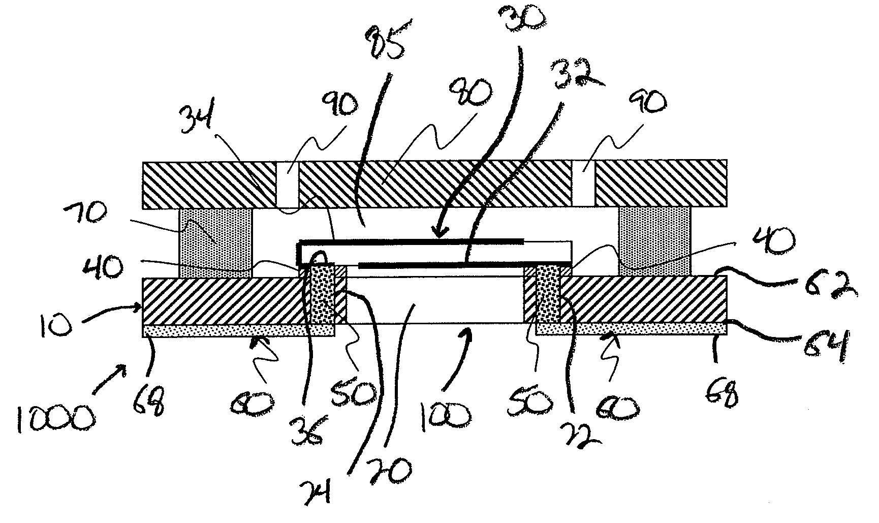
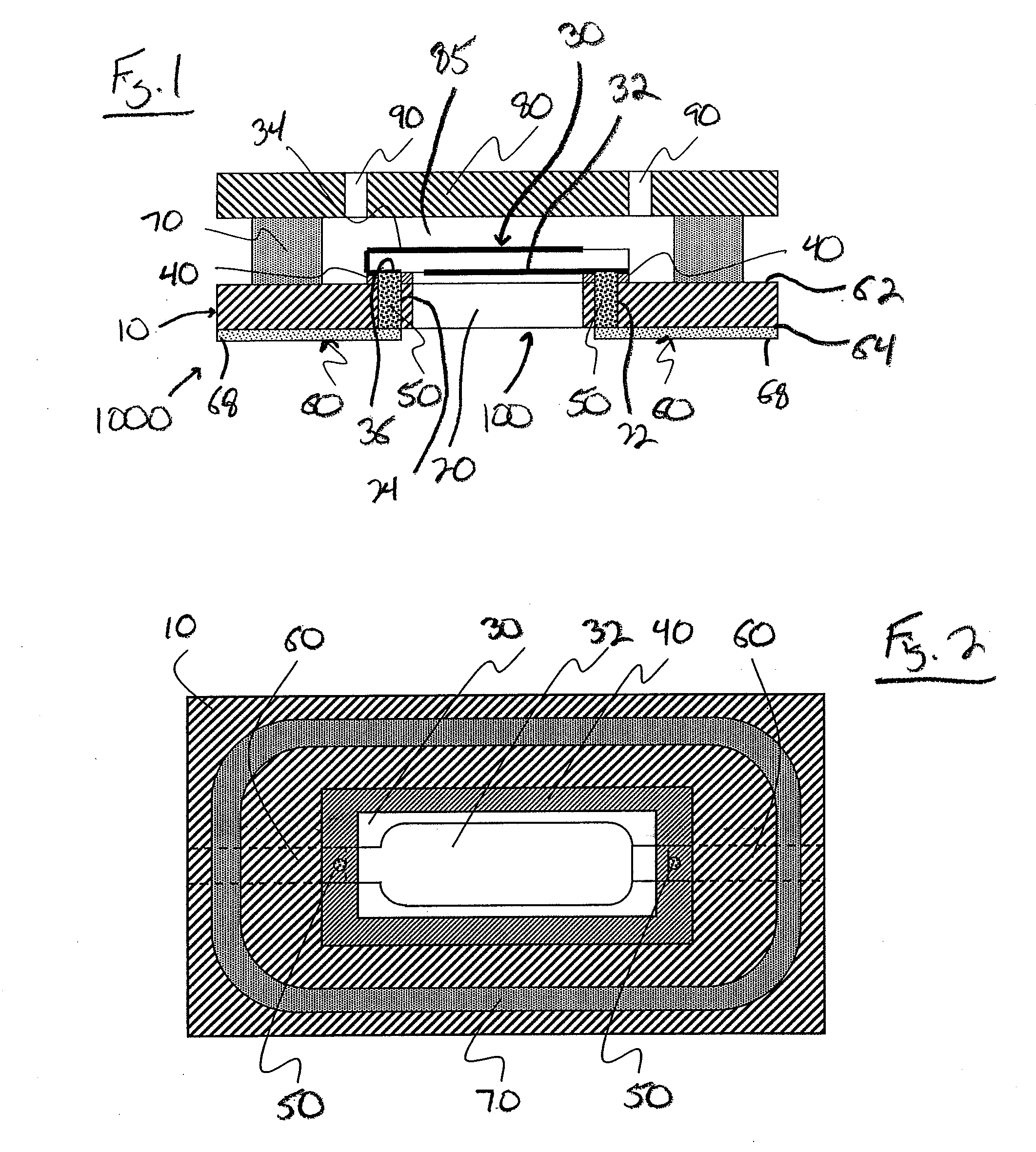
[0022]With reference now to the drawing figures in which like reference numerals represent like parts throughout the disclosure, a sensor assembly constructed according to the present invention is illustrated generally at 100 in FIG. 1. In one embodiment for the assembly shown in FIG. 1, the assembly 100 is a dry side sensor mounting assembly for a single sensing spot crystal resonator 30 assembled into a sample delivery flow cell 1000. The assembly 100 is formed with a substrate 10 of a fluid-impervious and non-conductive material that includes a central bore 20 and a pair of electrode contact bores 22, 24 disposed on opposite sides of the central bore 20, though the bores 22, 24 can be located in any suitable location around the bore 20. Additionally, the central bore 20 and the bores 22, 24 are shaped as desired to accommodate the particular structure of the assembly 100, and therefore can have any desired shape.

[0023]An oscillating crystal resonator 30 formed of a conventional quar


PUM

PropertyMeasurementUnit
Flow rateaaaaaaaaaa
Electrical conductoraaaaaaaaaa
Adhesivityaaaaaaaaaa

Abstract

An assembly design for an oscillating resonator-based sensor where an oscillating crystal resonator such as a quartz crystal resonator is rigidly affixed or ‘mounted’ onto a solid substrate in such a fashion that the resonator can either rest flush against the substrate surface or upon a rigid mounting adhesive. Once cured, the mounting adhesive forms a liquid tight seal between the mounted resonator and the substrate such that only the sensing electrode surface will be exposed to fluids applied to the front side of the substrate. The mounted resonator assembly is designed in such a way that it can be interfaced with a fluid delivery system to form a liquid tight chamber or flow cell around the mounted resonator without incurring additional physical impact upon the mounted resonator. The assembled flow cell can in turn be used to direct multiple fluid streams to flow in a laminar manner over the sensing surface of the mounted resonator and by varying the rates of flow for the different laminar flowing fluid streams the total hydraulic pressure exerted on the surface of the mounted resonator can be held constant.

Description


Claims


Application Information

Patent Timeline
Owner BRUKER DALTONIK GMBH & CO KG
Why Eureka
Try Eureka