Inline vacuum processing apparatus, method of controlling the same, and information recording medium manufacturing method

a vacuum processing and vacuum technology, applied in the direction of plasma technique, metal material coating process, coating, etc., can solve the problems of affecting the production efficiency of the entire production line, so as to shorten the time of carbon protective film formation and improve the production efficiency without bulky and expensive apparatus

Active Publication Date: 2010-07-01
CANON ANELVA CORP
View PDF30 Cites 4 Cited by
  • Summary
  • Abstract
  • Description
  • Claims
  • Application Information

AI Technical Summary

Benefits of technology

The technical effect of this patented technology is that it allows for faster and more efficient production while reducing the size and cost of equipment used during the process.

Problems solved by technology

The technical problem addressed in this patent text relates to reducing the time required for replacing the process gas during the carbon protective film formation process in a single chamber for substrate quality management. Specifically, current methods require multiple steps before changing the process gas for carbon protection, leading to increased complexity and reduced productivity.

Method used


Image

  • Inline vacuum processing apparatus, method of controlling the same, and information recording medium manufacturing method
  • Inline vacuum processing apparatus, method of controlling the same, and information recording medium manufacturing method
  • Inline vacuum processing apparatus, method of controlling the same, and information recording medium manufacturing method

Examples


Embodiment Construction

[0042]Preferred embodiments of the present invention will now be described exemplarily in detail with reference to the accompanying drawings. Note that the constituent elements described in the embodiments are merely examples. The technical scope of the present invention is determined by the scope of claims and is not limited by the following individual embodiments.

[0043]The production line of an information recording medium (to be referred to as an “information recording disk” hereinafter) includes a load lock chamber to mount a substrate on a carrier, an unload lock chamber to unload the substrate from the carrier, and chambers to execute a plurality of manufacturing processes. The chambers are connected in series and arranged in a line or in a rectangular form, thereby forming an information recording disk production line.

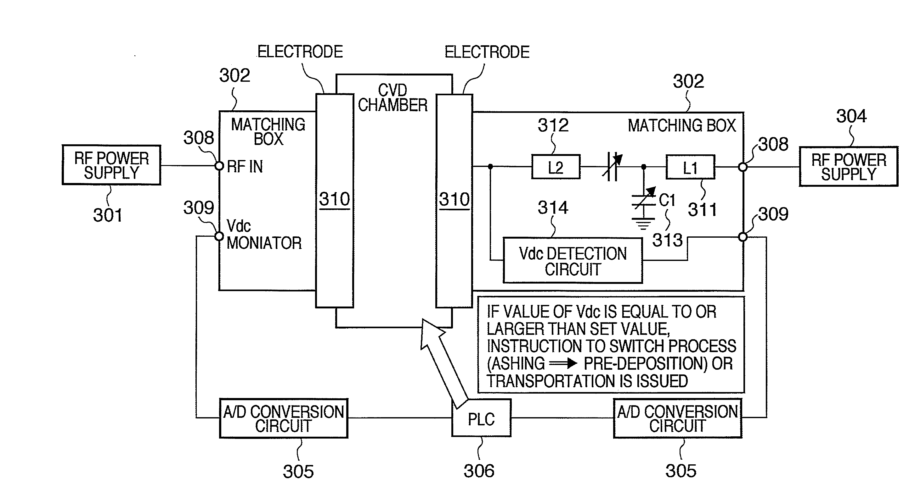
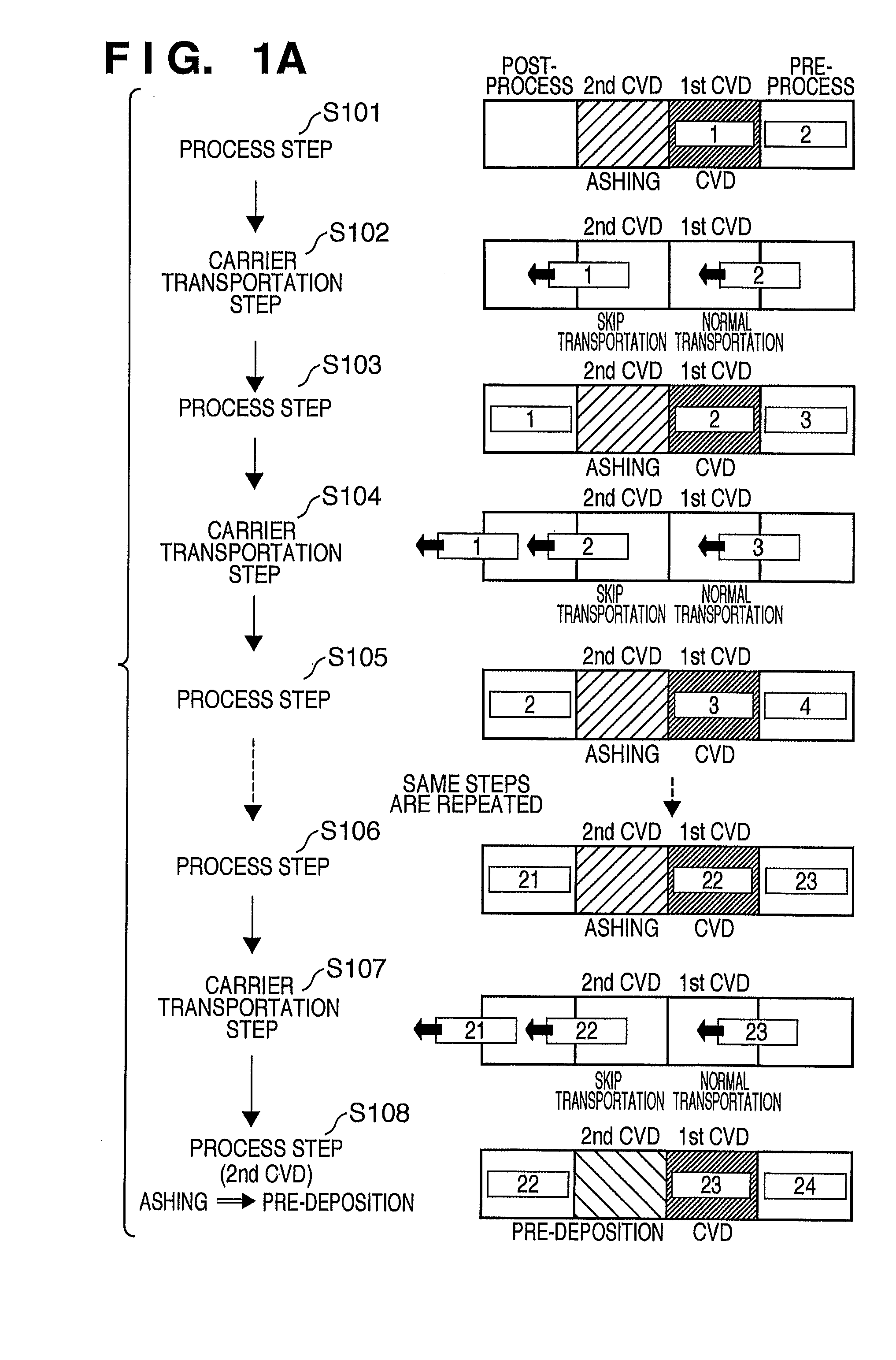
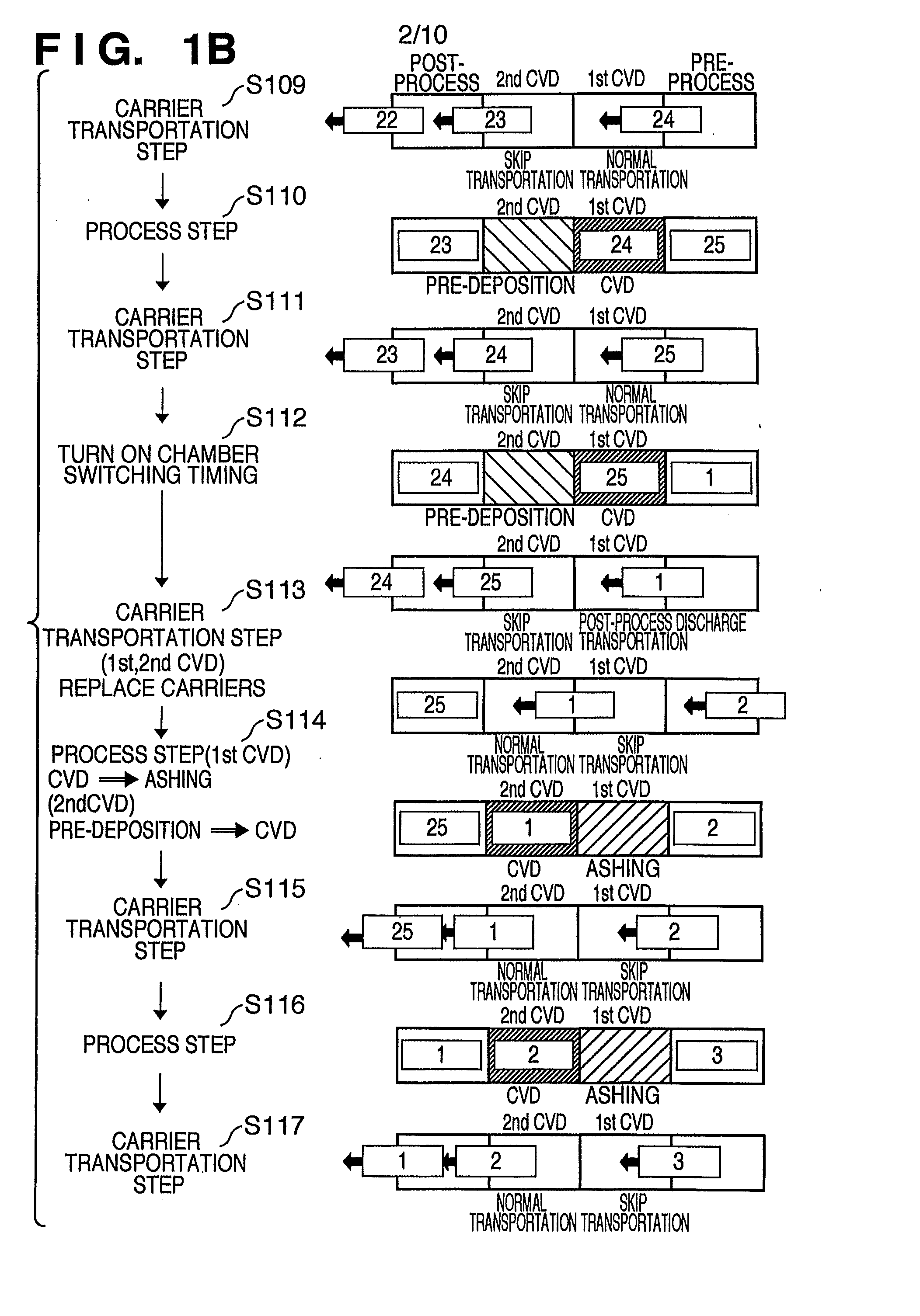
[0044]FIGS. 1A to 1C are schematic views showing a partial arrangement of an inline vacuum processing apparatus according to the embodiment of the present inventio


PUM

PropertyMeasurementUnit
Concentrationaaaaaaaaaa
Electric potential / voltageaaaaaaaaaa

Abstract

An inline vacuum processing apparatus includes a deposition unit, a process execution unit, a determination unit, and a control unit. The deposition unit causes one deposition chamber of a first deposition chamber and a second deposition chamber to execute a deposition process. The process execution unit causes the other deposition chamber to execute a process necessary for the deposition process. The determination unit measures the number of substrates processed in one deposition chamber and determines whether all substrates included in a first lot have undergone the deposition process. The control unit switches, based on a determination result from the determination unit, a process to be executed in each of the first deposition chamber and the second deposition chamber.

Description


Claims


Application Information

Patent Timeline
Owner CANON ANELVA CORP
Why Eureka
Try Eureka