Reaction treatment apparatus and reaction treatment method
- Summary
- Abstract
- Description
- Claims
- Application Information
AI Technical Summary
Benefits of technology
Problems solved by technology
Method used
Image

Examples
embodiment 1
[0047]Hereinafter, Embodiment 1 to which the present invention may be applied is described with reference to FIGS. 1, 2A and 2B, and 3.
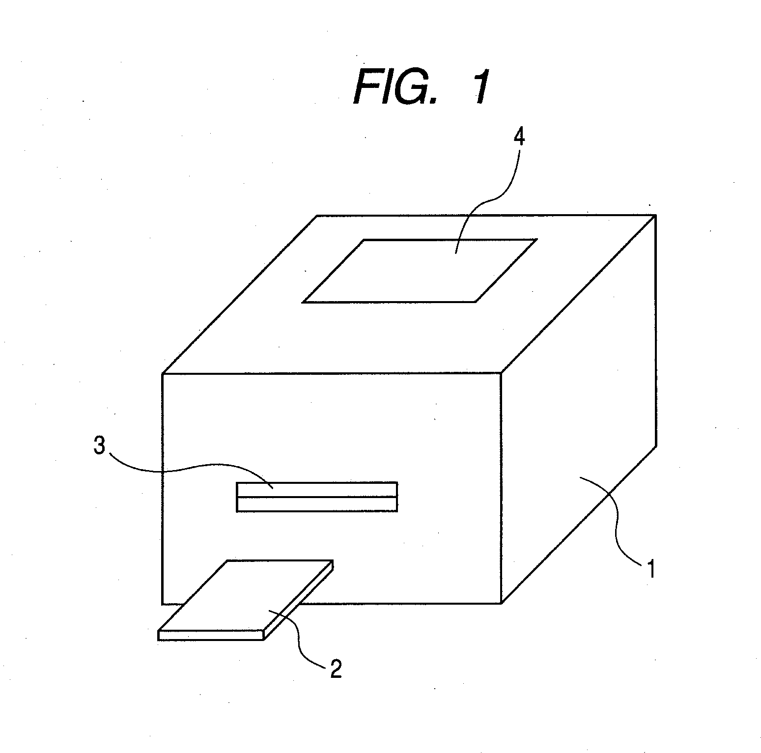
[0048]FIG. 1 is a perspective view of a biochemical reaction system. The biochemical reaction system 1 has a set portion 3 through which a microchip 2 is inserted or discharged. On an upper surface of the biochemical reaction system 1, a display portion 4 displaying an operation state, an inspection result, etc., is provided.
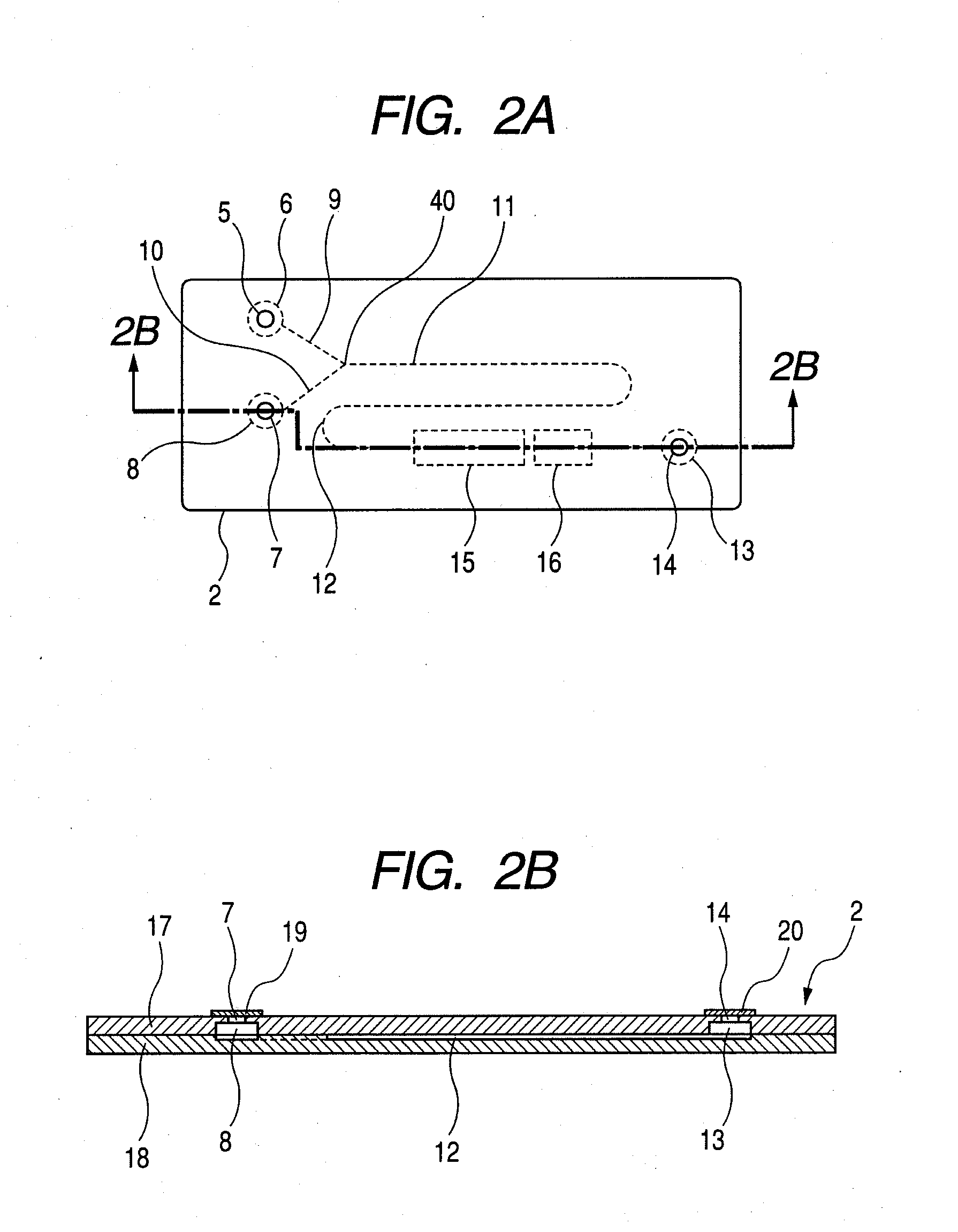
[0049]FIG. 2A is a plan view of the microchip. The microchip 2 has a first introduction port 5 and a second introduction port 7, and the first introduction port 5 communicates with a first chamber 6. The first chamber 6 communicates with a first upstream fluid path 9. The first upstream fluid path 9 communicates with a merged fluid path 11. The merged fluid path 11 communicates with a main fluid path 12. The main fluid path 12 communicates with a first waste liquid chamber 13. The first waste liquid chamber 13 communicates with a fi
embodiment 2
[0056]Hereinafter, Embodiment 2 to which the present invention may be applied is described with reference to FIG. 4.
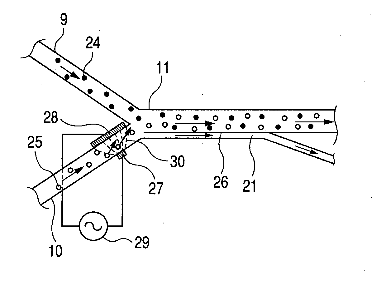
[0057]FIG. 4 is an enlarged view of the vicinity of a merged portion of upstream fluid paths. In Embodiment 2, positions of a first electrode 44 and a second electrode 45 are changed with respect to Embodiment 1. The remaining configuration is the same as that of Embodiment 1. The merged fluid path 11 is provided with the first electrode 44 and the second electrode 45 opposed to each other. The first electrode 44 and the second electrode 45 are electrically connected to the AC power source 29. A portion of the first electrode 44 in which the first electrode 44 is brought into contact with the merged fluid path 11 is formed smaller than a portion of the second electrode 45 in which the second electrode 45 is brought into contact with the merged fluid path 11. Since the portion in which the first electrode 44 is brought into contact with the merged fluid path 11 is differen
embodiment 3
[0058]Hereinafter, Embodiment 3 to which the present invention may be applied is described with reference to FIGS. 5A, 5B, and 5C.
[0059]FIG. 5A is a plan view of a microchip 2. In Embodiment 3, a first branched fluid path 21, a second waste liquid chamber 22, and a second opening 23 are added to Embodiment 1. The remaining configuration is the same as that of Embodiment 1. The merged fluid path 11 communicates with the first branched fluid path 21. The first branched fluid path 21 communicates with the second waste liquid chamber 22. The second waste liquid chamber 22 communicates with the second opening 23. A sheet (not shown) is attached to the second opening 23 so as to prevent foreign matter from entering the microchip 2 through the second opening 23. As described with reference to FIGS. 1 and 2A in Embodiment 1, when the microchip 2 is inserted in the set portion 3 of the biochemical reaction system 1, openings are formed in the sheets by the perforating member provided in the bio
PUM
| Property | Measurement | Unit |
|---|---|---|
| Time | aaaaa | aaaaa |
| Concentration | aaaaa | aaaaa |
| Area | aaaaa | aaaaa |
Abstract
Description
Claims
Application Information
 - R&D Engineer
- R&D Manager
- IP Professional
- Industry Leading Data Capabilities
- Powerful AI technology
- Patent DNA Extraction
Browse by: Latest US Patents, China's latest patents, Technical Efficacy Thesaurus, Application Domain, Technology Topic.
© 2024 PatSnap. All rights reserved.Legal|Privacy policy|Modern Slavery Act Transparency Statement|Sitemap