Dock leveler for loading dock with integral on-demand compressor and pneumatic actuator

Inactive Publication Date: 2011-10-27
BLUE GIANT EQUIPMENT CORPORATION
View PDF2 Cites 9 Cited by
  • Summary
  • Abstract
  • Description
  • Claims
  • Application Information

AI Technical Summary

Benefits of technology

[0012]Further, the deck can include a lip plate hingedly mounted to a front edge thereof, the deck including a pneumatic lip actuator pivotally connected to the lip plate for rotary movement between a deployed position and a retracted position, the lip actuator having a deploy chamber, and an inlet port in direct communication with the compressor outlet through an electric powered lip deploy valve to the deploy chamber, and having a vent valve in communication with the deploy chamber. The electric user control interface may also have an electric deploy/retract switch in communication with the motor to conduct electric power to the motor a

Problems solved by technology

The dock leveler may be easily installed and maintained in environments that do not have compressed air a

Method used


Image

  • Dock leveler for loading dock with integral on-demand compressor and pneumatic actuator
  • Dock leveler for loading dock with integral on-demand compressor and pneumatic actuator
  • Dock leveler for loading dock with integral on-demand compressor and pneumatic actuator

Examples


Embodiment Construction

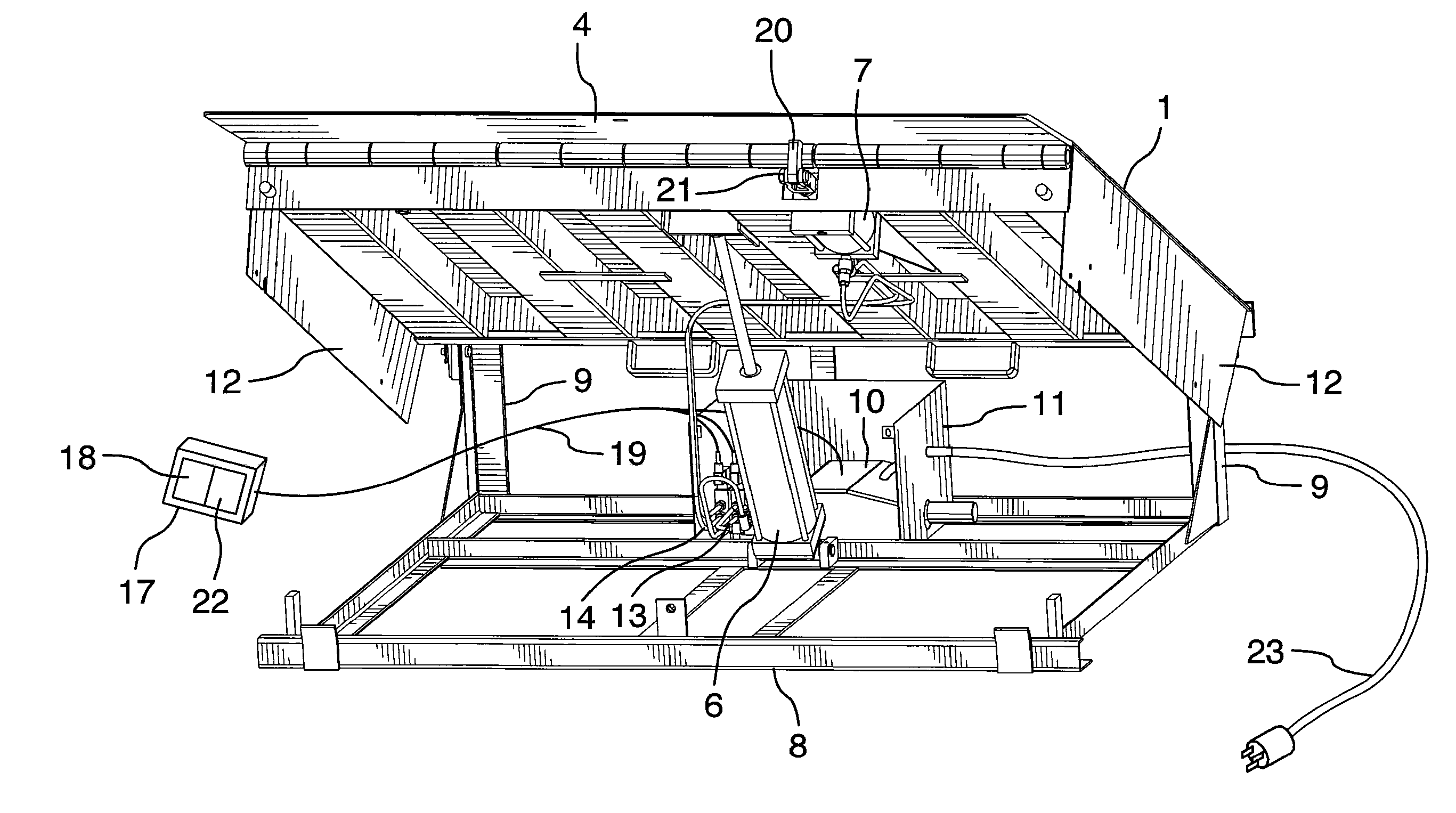
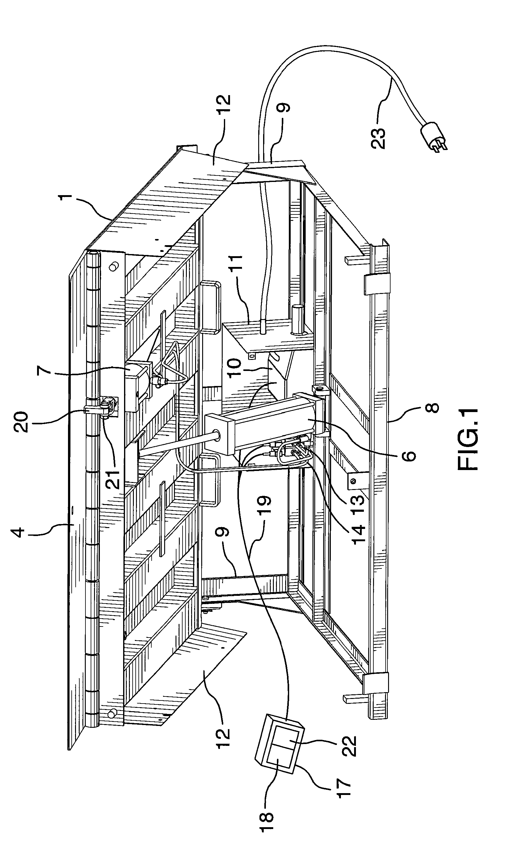
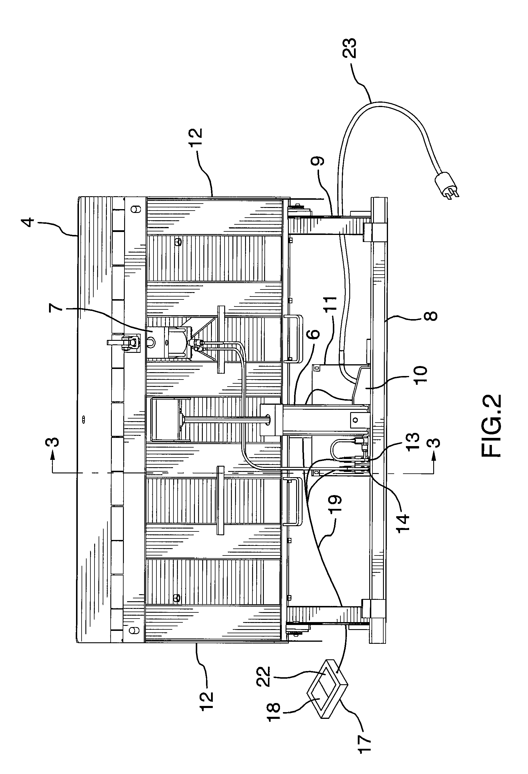
[0021]FIGS. 1-3 show the loading dock leveler which is generally rectangular and fits within a rectangular threshold recess adjacent a truck loading doorway in a building, or in the edge of a raised dock platform. The dock platform, and floor of the building are at the level of the rear of the dock leveler. The building and doorway are not shown since such arrangements are commonly known to those skilled in the art.

[0022]FIG. 3 shows the movable deck 1 of the dock leveler with a top platform surface on which wheeled vehicles, people or animals travel. The deck 1 pivots relative to the building floor 2 about a hinge pin 3. The outside lip plate 4 is relatively thin and of relatively short length to pivot on a pin 5 on the outside end of the main deck 1 and when lowered the lip plate 4 provides a smooth transition between the truck deck surface and adjacent main deck 1. The pneumatic lift actuator 6 moves the deck 1 of the dock leveler between the upper position and the lower position, a


PUM


Abstract

A loading dock leveler having: a base having an inward end; a deck with a top platform, the deck having an inward end hingedly mounted to the inward end of the base for movement between an upper position and a lower position; an on-demand air compressor with an electrically powered motor, the compressor having inlet in communication with a source of ambient air and a compressed air outlet; a pneumatic deck lift actuator pivotally connected to the base and to the deck for rotary movement between a raised position and a lowered position, the lift actuator having a lift chamber, and an inlet port in direct communication with the compressor outlet through an electric powered lift valve to the lift chamber, and having a vent valve in communication with the lift chamber; and an electric user control interface having: an electric up/down switch in communication with the motor to conduct electric power to the motor and open the lift valve in an up position, and to prevent conduction of electric power to the motor and open the vent valve in a down position; wherein the compressor, motor, lift valve; vent valve and lift actuator are disposed between the base and the deck.

Description


Claims


Application Information

Patent Timeline
Owner BLUE GIANT EQUIPMENT CORPORATION
Why Eureka
Try Eureka