Vehicle control apparatus
a technology of vehicle control and control apparatus, which is applied in the direction of jet propulsion, process and machine control, and propulsion using engine-driven generators. it can solve the problems of deteriorating drivability, increasing the shock perception of the driver, and practicable difficulty in suppressing it to zero, so as to reduce the shock of the torque of the input shaft, reduce the speed and suppress the sudden change of the input shaft torque
- Summary
- Abstract
- Description
- Claims
- Application Information
AI Technical Summary
Benefits of technology
Problems solved by technology
Method used
Image


Examples
first embodiment
Structure of Embodiment
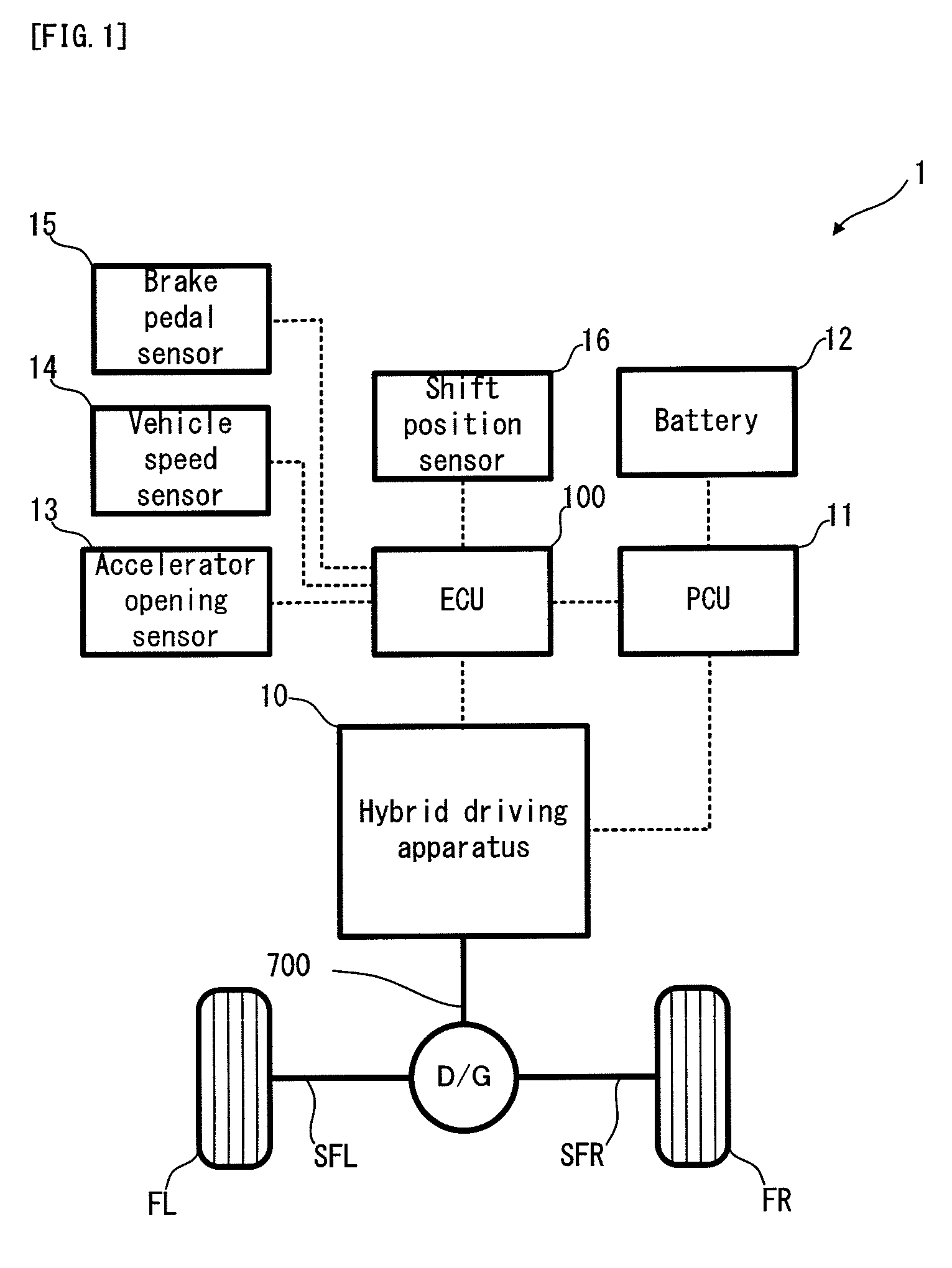
[0075]Firstly, with reference to FIG. 1, an explanation will be given on the structure of a hybrid vehicle 1 in a first embodiment of the present invention. FIG. 1 is a schematic configuration diagram conceptually showing the structure of the hybrid vehicle 1.
[0076]In FIG. 1, the hybrid vehicle 1 is a hybrid vehicle as one example of the “vehicle” of the present invention, provided with: an ECU 100; a PCU (Power Control Unit) 11; a battery 12; an accelerator opening sensor 13; a vehicle speed sensor 14; a brake pedal sensor 15; a shift position sensor 16 and a hybrid drive apparatus 10.
[0077]The ECU 100 is provided with a CPU (Central Processing Unit), a ROM (Read Only Memory), a RAM and the like. The ECU 100 is an electronic control unit capable of controlling the operations of each part of the hybrid vehicle 1. The ECU 100 is one example of the “vehicle control apparatus” of the present invention. The ECU 100 can perform speed change control described alter, in
second embodiment
[0187]The structure of the hybrid drive apparatus is not limited to that of the hybrid drive apparatus 10 in the first embodiment. Now, with reference to FIG. 14, an explanation will be given on the structure of a hybrid drive apparatus 20 in a second embodiment of the present invention. FIG. 14 is a schematic configuration diagram conceptually showing the structure of the hybrid drive apparatus 20. Incidentally, in FIG. 14, the overlap points with FIG. 2 will carry the same reference numerals, and the explanation thereof will be omitted as occasion demands.
[0188]In FIG. 14, the hybrid drive apparatus 20 is constructed such that the drive shaft 500 and the input shaft 600 are selectively controlled into the engagement or disengagement state by a clutch 900. Moreover, between the motor generator MG2 and the input shaft 600, there is disposed a MG2 reduction mechanism 800 capable of decelerating the MG2 rotational speed Nm at two stages.
[0189]The MG2 reduction mechanism 800 is provided w
third embodiment
[0191]The structure of the hybrid drive apparatus is not limited to that of the hybrid drive apparatus 10 in the first embodiment. Now, with reference to FIG. 15, an explanation will be given on the structure of a hybrid drive apparatus 30 in a third embodiment of the present invention. FIG. 15 is a schematic configuration diagram conceptually showing the structure of the hybrid drive apparatus 30. Incidentally, in FIG. 15, the overlap points with FIG. 2 will carry the same reference numerals, and the explanation thereof will be omitted as occasion demands.
[0192]In FIG. 15, the hybrid drive apparatus 30 has a stepless transmission part 1000 and a stepped transmission part 1100. The stepless transmission part 1000 is provided with: a planetary gear unit, which is conceptually equal to the power dividing mechanism 300 in the hybrid drive apparatus 10; and a reduction gear for decelerating the MG2 rotational speed Nm, and it functions as a 2-degree-of-freedom differential mechanism as in
PUM
 Abstract
Description
Claims
Application Information
 - R&D Engineer
- R&D Manager
- IP Professional
- Industry Leading Data Capabilities
- Powerful AI technology
- Patent DNA Extraction
Browse by: Latest US Patents, China's latest patents, Technical Efficacy Thesaurus, Application Domain, Technology Topic.
© 2024 PatSnap. All rights reserved.Legal|Privacy policy|Modern Slavery Act Transparency Statement|Sitemap