Collet for quick connect tube coupling and a mold apparatus for making the same

a quick-connect tube and mold technology, applied in the field of quick-connect tube coupling and mold apparatus for making the same, can solve the problem of short lifespan and achieve the effect of long lifespan

Inactive Publication Date: 2012-12-06
KOUW PINNQ ENTERPRISE
View PDF5 Cites 4 Cited by
  • Summary
  • Abstract
  • Description
  • Claims
  • Application Information

AI Technical Summary

Benefits of technology

The technical effect of this patented design is that it uses a female mold segment without any protrusions on its surface, which makes it longer lasting than traditional designs.

Problems solved by technology

This patent describes various technical features related to a collet used in a mold assembly for crimping tubular components such as pipes. These fittings allow for easy insertion and removal of the component without damage during manufacturing. They also provide stability during operation.

Method used


Image

  • Collet for quick connect tube coupling and a mold apparatus for making the same
  • Collet for quick connect tube coupling and a mold apparatus for making the same
  • Collet for quick connect tube coupling and a mold apparatus for making the same

Examples


Embodiment Construction

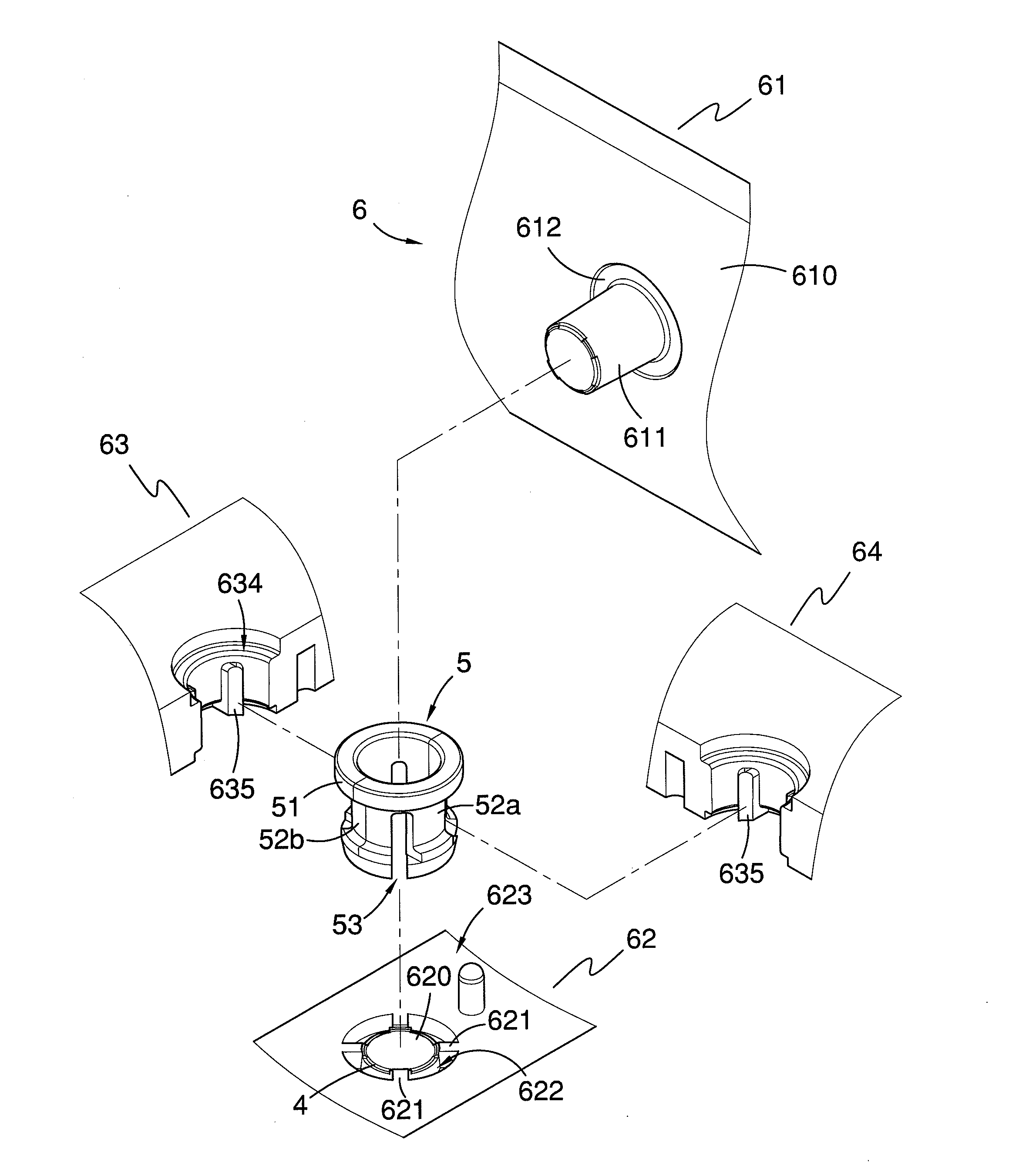
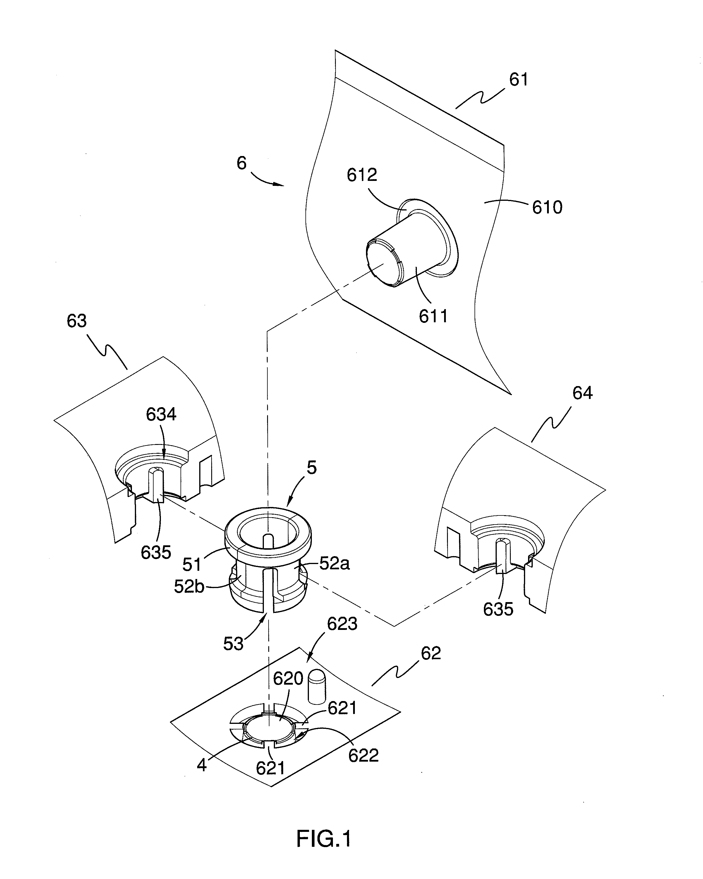
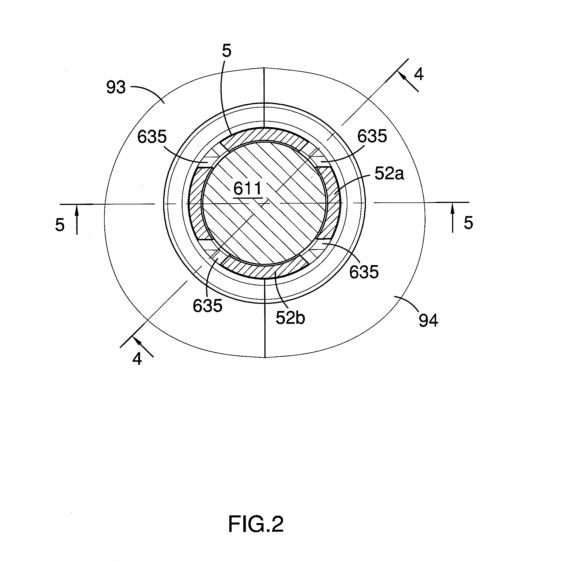
[0042]Referring now to FIGS. 1 through 10 of the drawings, there are shown a collet 5 and a mold apparatus 6 in accordance with the preferred embodiment of the invention. The collet 5 is molded in one piece from plastic for locking a tube in a tube coupling body (not shown) and generally includes an annular collar 51 and four arms 52a, 52b extending from the collar 51 in a direction generally parallel to the axis of the collar 51. The four arms 52a, 52b are arranged in a circle and spaced a distance apart from one another by slots 53 for encircling the tube. The four arms 52a, 52b are composed of two pairs of arms 52a, 52b that are quite different from each other, as will be discussed later in detail.

[0043]To shape this type of collet 5, the mold apparatus 6 generally includes an upper male mold segment 61, a lower female mold segment 62 and two side opposing mold segments 63, 64. As shown in FIGS. 1 and 3, the upper male mold segment 61 has a base 610 and a mold core 611 extending fro


PUM

PropertyMeasurementUnit
Diameteraaaaaaaaaa

Abstract

A collet includes an annular collar and four arms extending from the collar. Each arm has a reduced outer diameter arcuate section, an enlarged outer diameter arcuate section and a tapered arcuate section with a fan-shaped cross section at a distal end. Further, each arm has a first mold witness line presented on a boundary between the enlarged outer diameter arcuate section and the tapered arcuate section. Besides, each of two opposing ones of the four arms has its opposite side surfaces parallel to each other along its reduced outer diameter arcuate section and its enlarged outer diameter arcuate section. Each of the other two opposing ones of the four arms has a second mold witness line presented along its reduced outer diameter arcuate section and its enlarged outer diameter arcuate section and terminating at the intersection with the first mold witness line.

Description


Claims


Application Information

Patent Timeline
Owner KOUW PINNQ ENTERPRISE
Why Eureka
Try Eureka