Battery module

a battery module and battery technology, applied in the field of batteries, can solve the problems of high cost, high cost, and high cost of battery modules, and achieve the effects of increasing assembling efficiency, reducing the number of screws used for connecting parallel cell units, and improving the assembling process

Inactive Publication Date: 2013-01-10
DELTA ELECTRONICS INC
View PDF5 Cites 7 Cited by
  • Summary
  • Abstract
  • Description
  • Claims
  • Application Information

AI Technical Summary

Benefits of technology

The invented battery modules have several advantages over existing designs: they simplify assembly process while maintaining high-quality electrical connections between cells; reduce the use of expensive materials during production processes or improve their overall effectiveness and durability through improved insulation measures such as lamination films on both sides of each unit's electrodes (metal foils) that help protect them from corrosion caused by external factors like rainwater). Additionally, these batteries may require less space than traditional methods because there will no longer be any extra parts attached around it. Overall, this innovation simplifies the structure and reduces costs compared to current solutions.

Problems solved by technology

Technological Problem: Current Prussian Cell (PC) type batteries have limitations due to insufficient contact between terminal points during voltage charge discharge cycles caused by excessively high temperatures generated from rapid changes in internal pressure inside the PC' s case. Additionally, there exist issues related to maintain reliable connections within the device after repeated use without causing permanent damages like corrosion and burning off. Therefore, technical problem addressed in this patents relating to improving these characteristics while reducing manufacturing costs involves developing improved methods for assembly processes involving prongs and tabs.

Method used


Image

  • Battery module
  • Battery module
  • Battery module

Examples


Embodiment Construction

[0030]The present invention will be apparent from the following detailed description, which proceeds with reference to the accompanying drawings, wherein the same references relate to the same elements.

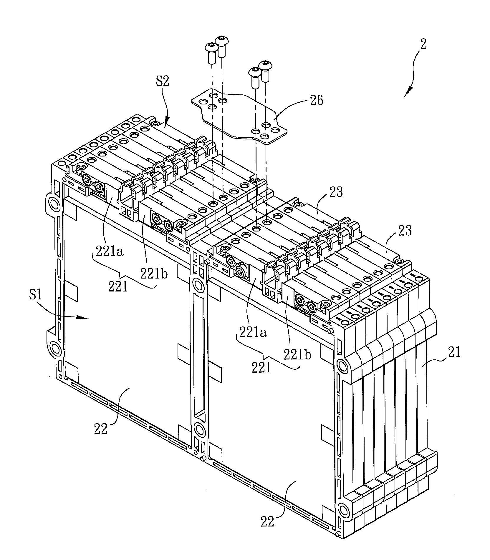
[0031]FIG. 3A is a schematic diagram of an assembled battery module 2 according to a preferred embodiment of the present invention, and FIG. 3B is a partial exploded view of the battery module 2. Referring to FIGS. 3A and 3B, the battery module 2 includes a plurality of cell units 20, which are stacked alone a direction Dl. Each cell unit 20 has a first surface S1 and a second surface S2, and includes a frame 21, at least one cell 22, and at least two conductors 23. In this embodiment, the battery module 2 includes 8 battery units 20, and each battery unit 20 includes two cells 22. The surface of the cell 22 is covered by insulating tapes for increasing its pressure resistance. The battery module 2 can be used as a vehicle battery module. In practice, multiple battery modules 2 are stack


PUM


Abstract

A battery module including a plurality of cell units is disclosed. Each cell unit has a first surface and a second surface, and the cell units are stacked alone a direction. The cell unit includes a frame, at least one cell and at least two conductors. The frame has at least a first accommodating recess located at the first surface. The cell having two tabs is accommodated in the first accommodating recess. The conductors and the frame are connected at the second surface, and each conductor has a connecting portion located at the first surface. The connecting portions of the two conductors are ultrasound welded with the two tabs respectively. The conductors of adjacent cell units are fixed to each other.

Description


Claims


Application Information

Patent Timeline
Owner DELTA ELECTRONICS INC
Why Eureka
Try Eureka