Display apparatus

a technology of display apparatus and display screen, which is applied in the direction of lighting and heating apparatus, static indicating devices, instruments, etc., can solve the problems of large inconvenience, discomfort and inconvenience, and substantial brightness reduction

Inactive Publication Date: 2013-07-04
IND TECH RES INST
View PDF0 Cites 30 Cited by
  • Summary
  • Abstract
  • Description
  • Claims
  • Application Information

AI Technical Summary

Benefits of technology

This patent describes a display device that uses multiple light sources for creating different colors in images displayed on it. Each source has its own unique structure and can be controlled separately or combined together to achieve various colored lights.

Problems solved by technology

This patent describes a problem with current methods used for displaying 3D content (stereoscopic) on displays that require special glasses worn during use. Additionally, there have also been concerns about how to improve the visual experience when users see 3D content displayed through these techniques.

Method used


Image

  • Display apparatus
  • Display apparatus
  • Display apparatus

Examples


Embodiment Construction

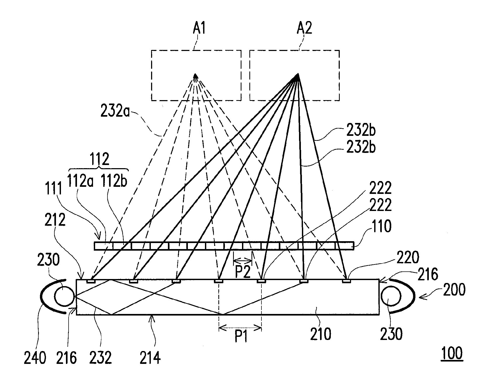
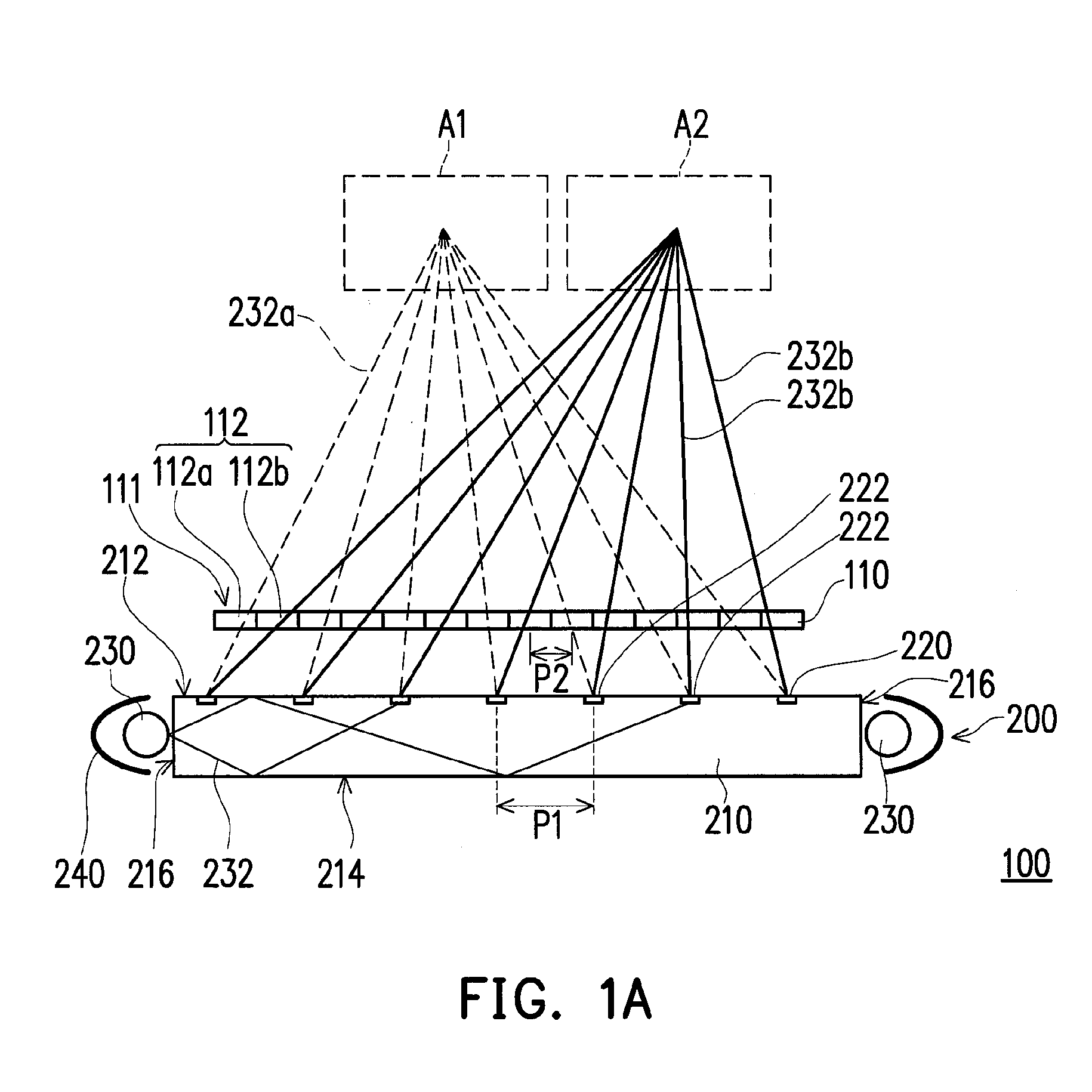
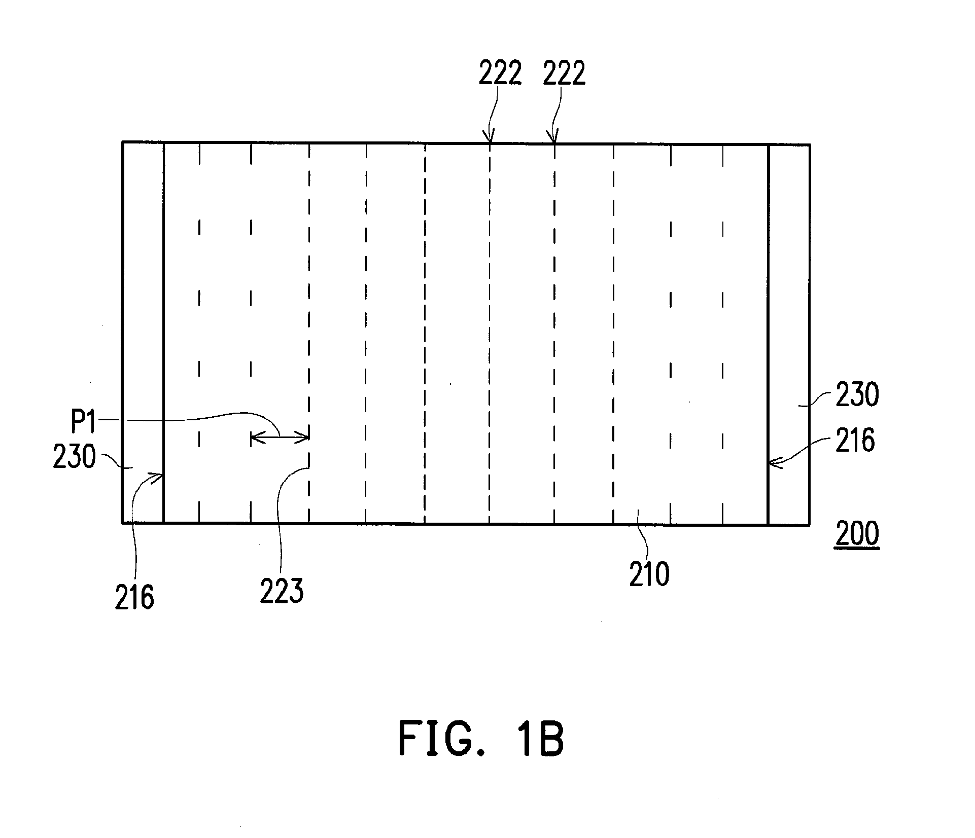
[0027]FIG. 1A is a schematic diagram showing a cross-sectional view of a display apparatus according to an exemplary embodiment of the disclosure, FIG. 1B is a top view diagram of the backlight module in FIG. 1A, while FIG. 1C illustrates the pixels of a transmissive display panel in FIG. 1A. In FIG. 1B, the lampshade in FIG. 1A is omitted to illustrate the position of the light emitting device. Referring to FIGS. 1A and 1B, the display apparatus 100 of this exemplary embodiment comprises a backlight module 200 and a transmissive display panel 110. The backlight module 200 comprises a light guide plate 210, a patterned scattering structure 220 and at least a light emitting device 230 (this embodiment, as illustrated in FIG. 1A, is exemplified with two light emitting devices 230). The light guide plate 210 comprises a first surface 212, a second surface 214 opposite to the first surface 212, and at least a light incident surface 216 (this embodiment, as illustrated in FIG. 1A, is exempl


PUM


Abstract

A display apparatus including a backlight module and a transmissive display panel is provided. The backlight module includes a light guide plate, a patterned light scattering structure, and a light emitting device. The light guide plate has a first surface, a second surface opposite to the first surface, and a light incident surface connecting the first surface and the second surface. The patterned light scattering structure is disposed on the light guide plate or inside the light guide plate. The patterned light scattering structure includes a plurality of light scattering strips. The light emitting device is configured to emit an illumination light and the light incident surface is disposed on the path of the illumination light. The light scattering strips are configured to scatter the illumination light. The transmissive display panel is disposed beside the backlight module. The first surface faces the transmissive display panel.

Description


Claims


Application Information

Patent Timeline
Owner IND TECH RES INST
Why Eureka
Try Eureka