Turbocharger and Variable-Nozzle Cartridge Therefor

a variable-nozzle, turbocharger technology, applied in the direction of positive displacement liquid engines, liquid fuel engines, piston pumps, etc., can solve the problems of reducing the efficiency of the turbine and hence the overall performance of the turbocharger, and the clearance effect is particularly harmful at low engine speed, so as to achieve the effect of reducing the performance penalty due to the clearance of the vane at low engine speed and achieving the effect of performance benefi

Active Publication Date: 2014-05-15
GARRETT TRANSPORATION I INC
View PDF0 Cites 3 Cited by
  • Summary
  • Abstract
  • Description
  • Claims
  • Application Information

AI Technical Summary

Benefits of technology

The technical effect of this patented technology relates to improving the efficiency with which certain parts inside an internal combustion engines work together during different stages or modes of operation. This results from placing a small amount outside the main part where fuel injection occurs instead of allowing them directly into the cylinders for better mixing between air-fuel mixture before ignition.

Problems solved by technology

Turbines within these engines use moving parts called valves or blades to adjust their operation based upon factors like pressure ratio and temperature. However, when trying to increase engine power without sacrificing some aspects such as reducing noise levels during high speed cruising conditions, it becomes difficult due to space constraints. Variable geometric turbositors provide more flexibility but they also require precise positioning of certain components inside them. These issues make designing better ways to improve turbocharge systems while maintaining good energy conversion capabilities remains problematic.

Method used


Image

  • Turbocharger and Variable-Nozzle Cartridge Therefor
  • Turbocharger and Variable-Nozzle Cartridge Therefor
  • Turbocharger and Variable-Nozzle Cartridge Therefor

Examples


Embodiment Construction

[0015]The present inventions now will be described more fully hereinafter with reference to the accompanying drawings, in which some but not all embodiments of the inventions are shown. Indeed, these inventions may be embodied in many different forms and should not be construed as limited to the embodiments set forth herein; rather, these embodiments are provided so that this disclosure will satisfy applicable legal requirements. Like numbers refer to like elements throughout.

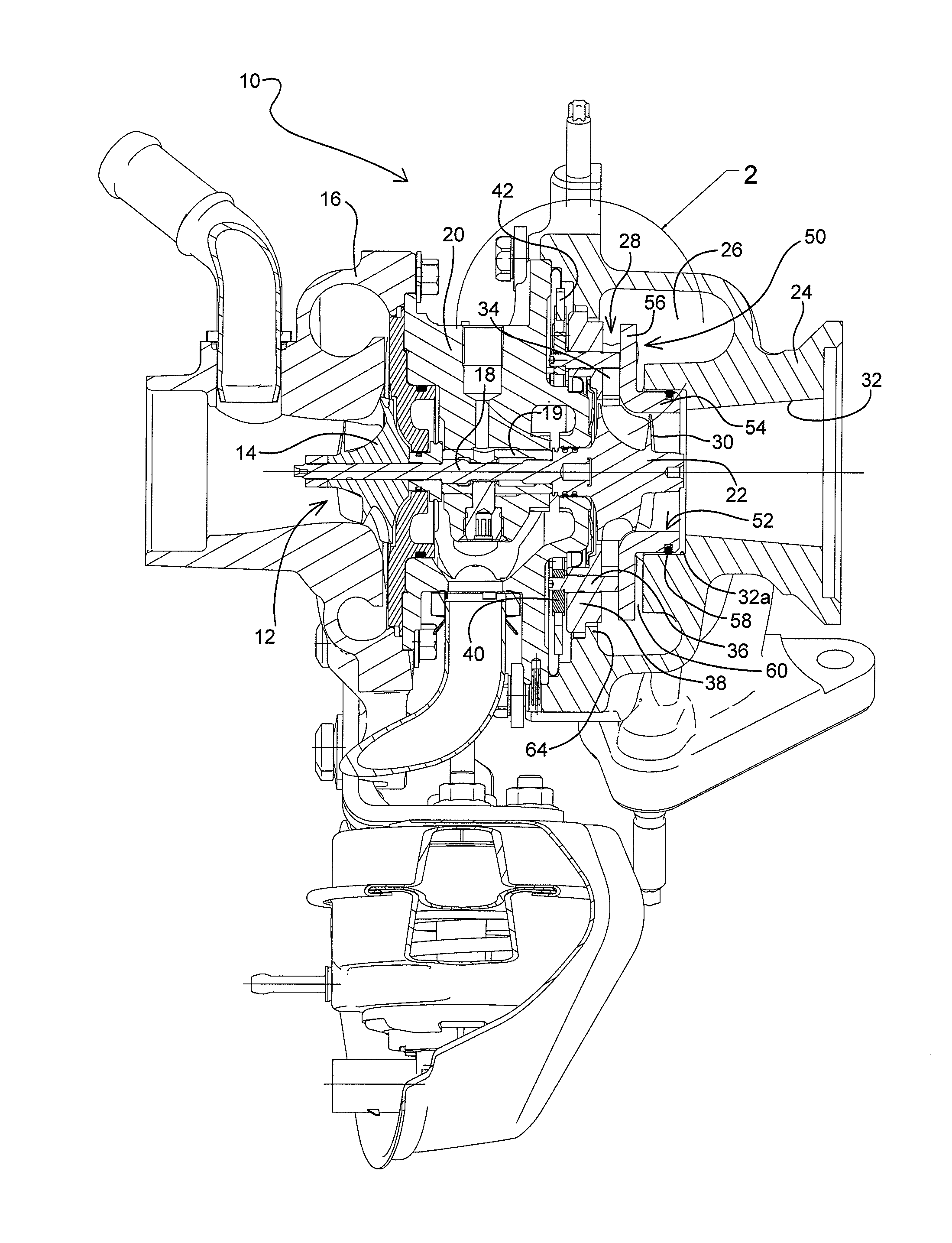
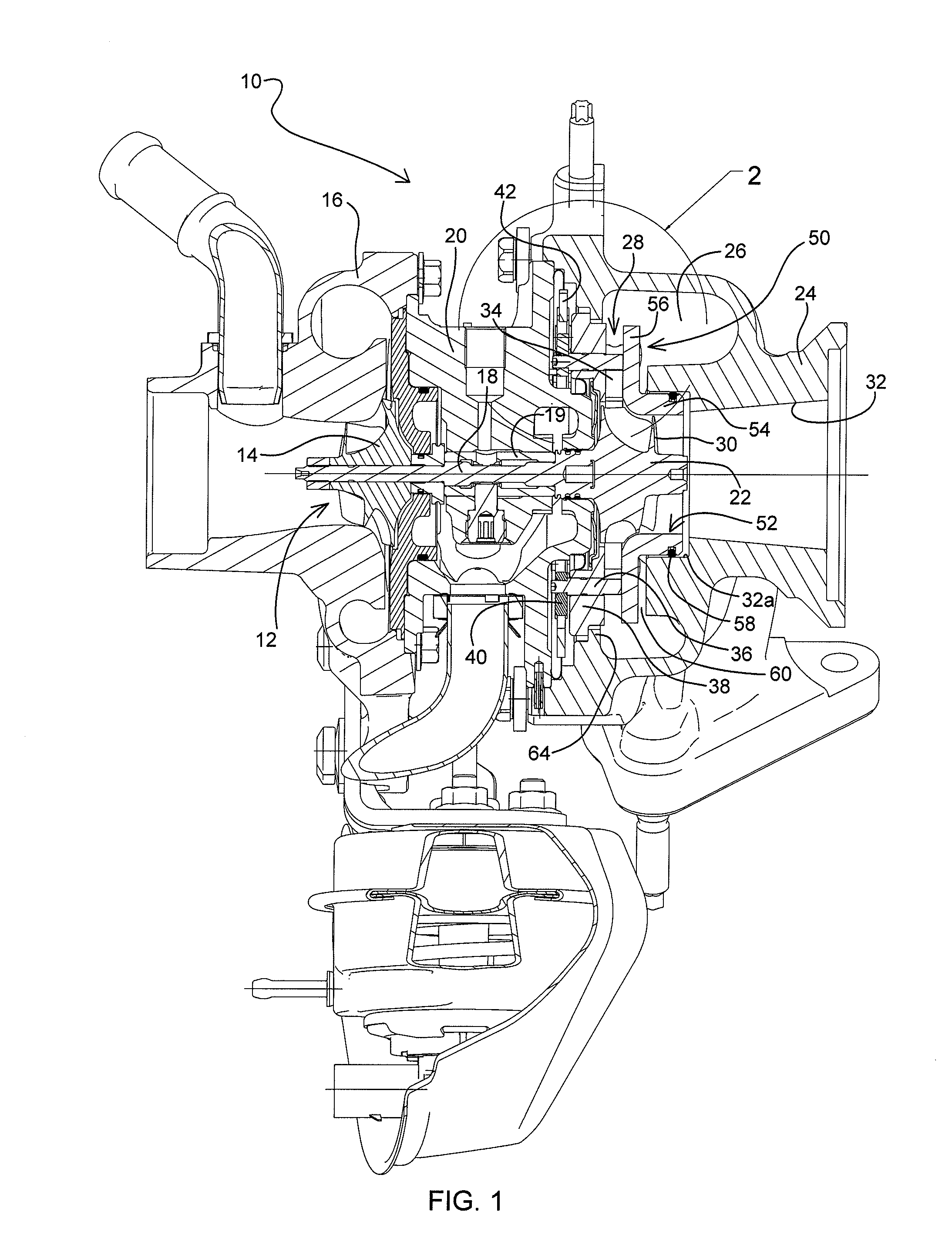
[0016]A turbocharger 10 in accordance with one embodiment of the invention is illustrated in cross-sectional view in FIG. 1. The turbocharger comprises a compressor 12 having a compressor wheel or impeller 14 mounted in a compressor housing 16 on one end of a rotatable shaft 18. The shaft is supported in bearings 19 mounted in a center housing 20 of the turbocharger. The shaft 18 is rotated by a turbine wheel 22 mounted on the other end of the shaft 18 from the compressor wheel, thereby rotatably driving the compr


PUM


Abstract

A variable-vane assembly for a turbocharger includes an annular nozzle ring supporting an array of rotatable vanes, an insert having a tubular portion sealingly received into the bore of the turbine housing and having a nozzle portion extending radially out from one end of the tubular portion and being axially spaced from the nozzle ring with the vanes therebetween, and an annular retainer ring disposed radially outward of the nozzle ring and extending generally radially inwardly. The nozzle ring's face is stepped, and a radially inner edge of the retainer ring engages the face of the nozzle ring radially outward of the step, the radially inner edge of the retainer ring having an axial thickness that is less than the step height such that a remaining portion of the step is presented to the exhaust gas flowing through the nozzle.

Description


Claims


Application Information

Patent Timeline
Owner GARRETT TRANSPORATION I INC
Why Eureka
Try Eureka