Virtual parallel load module system

a load module and virtual module technology, applied in the field of virtual parallel load module system, can solve the problems of inability to effectively combine multiple prior art devices are not capable of combining some of the load modules into a single virtual load, and lack of versatility

Inactive Publication Date: 2015-03-05
EXPERIUM TECH
View PDF1 Cites 0 Cited by
  • Summary
  • Abstract
  • Description
  • Claims
  • Application Information

AI Technical Summary

Benefits of technology

This patent describes a load system that can apply electrical power to different parts of a device called a voltage source. It consists of two loads - one connected to each part of the voltage source and another connected to other parts of the same circuit. Each load has its own controller and driver circuits. These systems are designed into a single unit where they work together.

Problems solved by technology

This patent describes a problem with existing load module systems: they cannot efficiently combine different load modules together into a single virtual load due to their limited ability to connect them in different ways. Additionally, previous designs were unable to allow certain load modules to share the same input current when needed.

Method used


Image

  • Virtual parallel load module system
  • Virtual parallel load module system
  • Virtual parallel load module system

Examples


Embodiment Construction

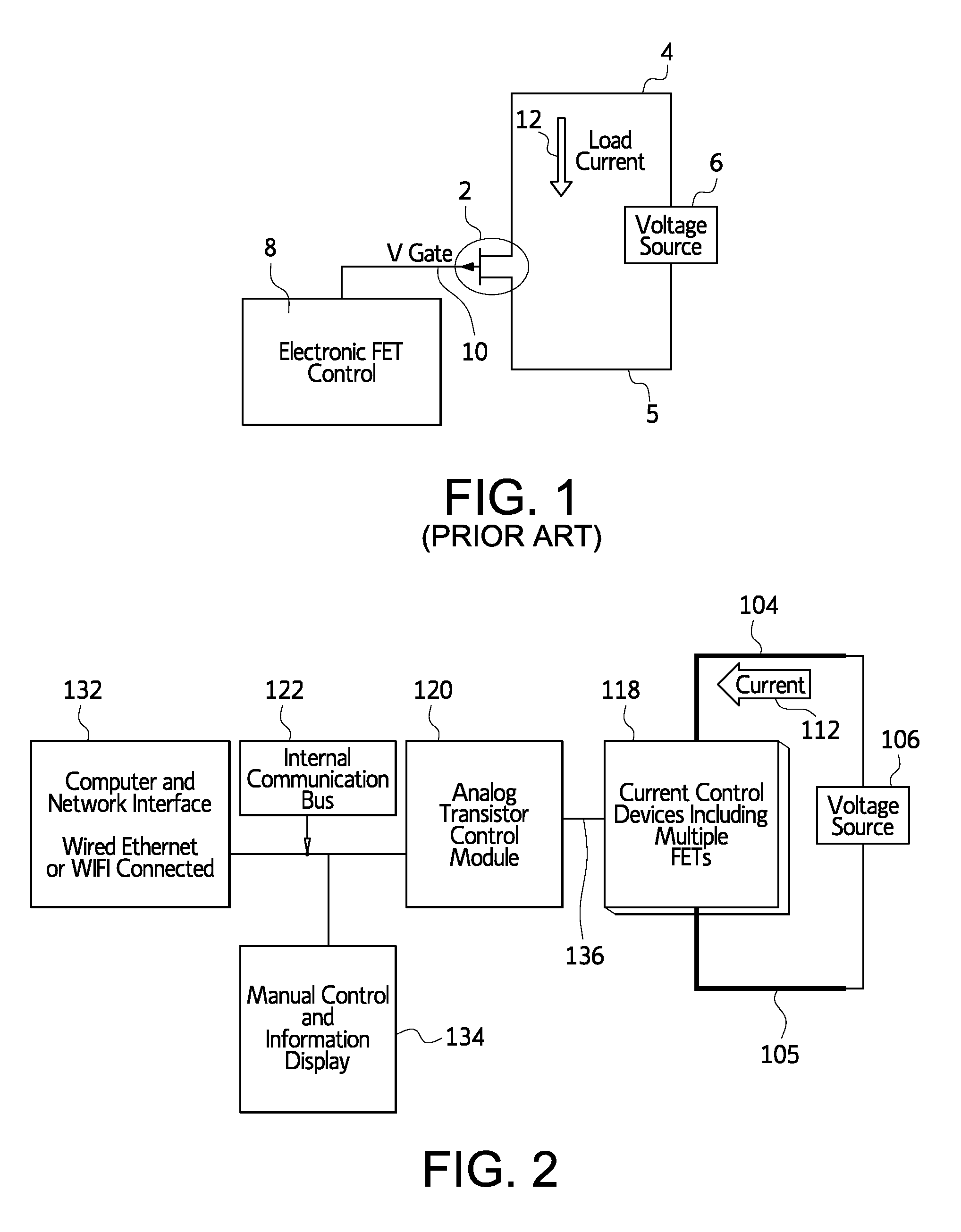
[0021]FIG. 1 shows load systems according to the prior art. In FIG. 1 there is shown a field effect transistor (FET) 2 connected across the terminals 4, 5 of a voltage source 6. The transistor is an electric device where the current through the device is controlled by the voltage applied to a specific terminal. In FIG. 1, the load current through two terminals of the transistor 2 is proportional to the voltage applied to the gate terminal. A current 12 passes between a source terminal 4 and a drain terminal 5. This current 12 may be referred to as the drain current (Idrain). The current 12 is proportional to a voltage applied to gate terminal 10. This voltage may be referred to as the gate voltage (Vgate). Accordingly, the FET can be modeled by the following simple equation:

Idrain=Constant*Vgate  [Eq. 1]

[0022]In embodiments of the invention, the gate terminal 10 is connected with an electronic FET controller 8. The controller 8 includes a digital to analog converter that provides the g


PUM


Abstract

An electronic load module system for testing voltage sources, such as power supplies, batteries, and fuel cells, is characterized by its ability to combine multiple load modules into a single virtual load for use with a first voltage source while simultaneously allowing other load modules in the same system to independently provide a load to an additional voltage source. The load modules may be combined in various configurations without altering the internal physical structure of the system. The system includes a first load module connected with the terminals of the voltage source and an associated control module connected with the first load module to supply a drive signal to the load module. The load system also includes a second load module. The second load module may be connected with the terminals of the voltage source in parallel with the first load module, or the second load module may be connected with the terminals of a second voltage source. A second control module is connected with the second load module to supply a drive signal to the second load module. The multiple load modules and control modules may be mounted in a single chassis.

Description


Claims


Application Information

Patent Timeline
Owner EXPERIUM TECH
Why Eureka
Try Eureka