Image recording apparatus and control method therefor
a technology of image recording and recording apparatus, applied in the direction of printing, etc., can solve the problems of image quality deterioration, sometimes impossible to perform proper control, and discontinuity in processing between divided areas, so as to reduce image deterioration and reduce processing speed
- Summary
- Abstract
- Description
- Claims
- Application Information
AI Technical Summary
Benefits of technology
Problems solved by technology
Method used
Image

Examples
first embodiment
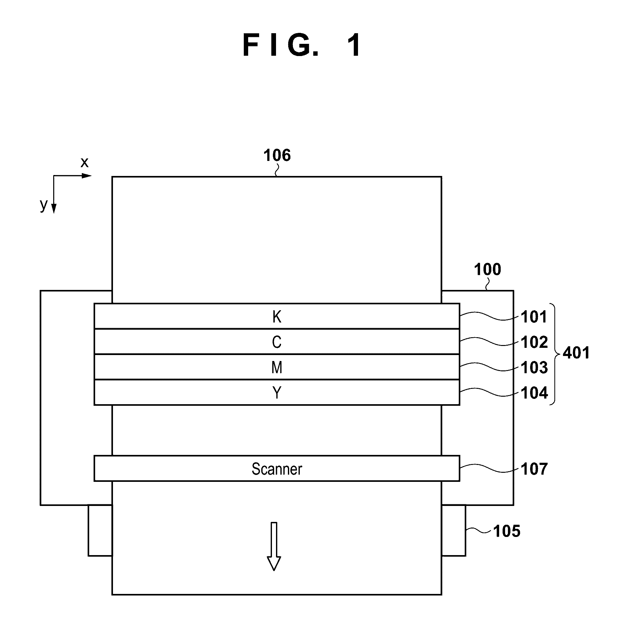
[0028]FIG. 1 is a view schematically showing a printer 100 as an inkjet recording apparatus according to the first embodiment. The printer 100 according to the embodiment is a full-line type recording apparatus, and includes recording heads 101 to 104, as shown in FIG. 1. Each of the recording heads 101 to 104 includes a nozzle array of a plurality of nozzles which correspond to the width of a recoding medium 106 and discharge the same type of ink. The nozzle array has nozzles arrayed in the x-axis direction in FIG. 1 at a pitch of 1,200 dpi. The recording heads 101 to 104 are recording heads which respectively discharge black (K), cyan (C), magenta (M), and yellow (Y) inks. The recording heads 101 to 104 which discharge these different types of inks are arranged in parallel in the y-axis direction in FIG. 1. Reference numeral 401 in FIG. 1 generically denotes the recording heads 101 to 104, which will be referred to as the recording head unit 401 hereinafter.
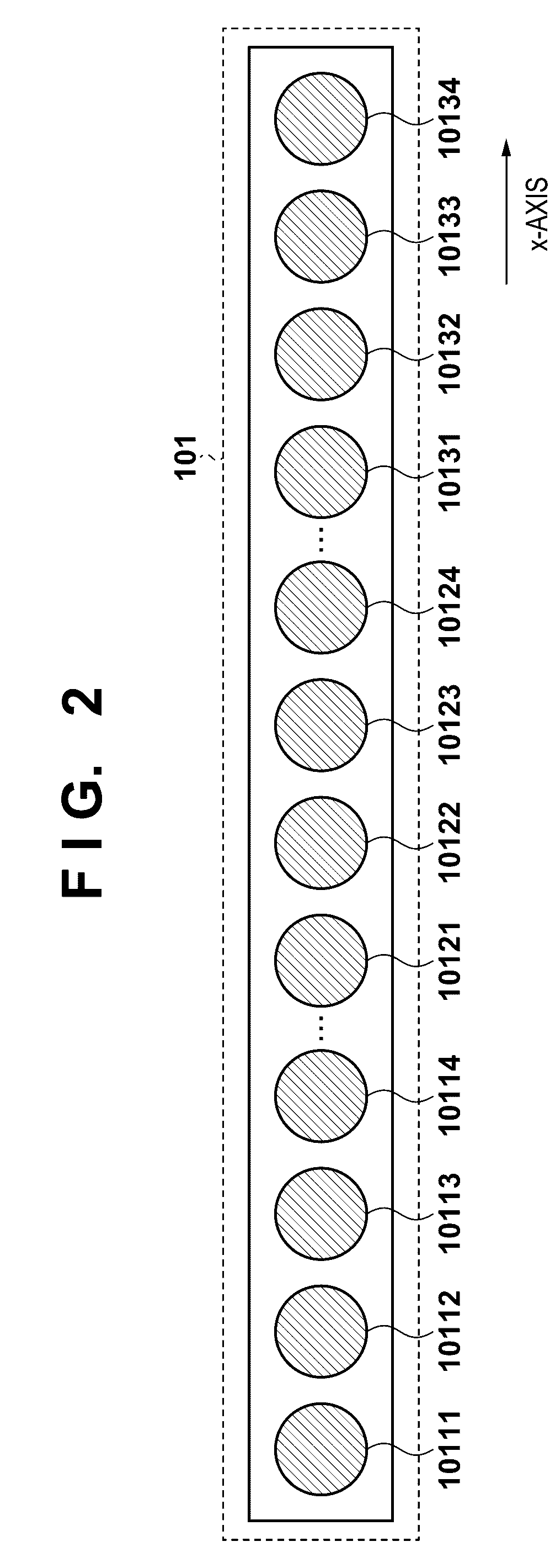
[0029]FIG. 2 is a view sho
second embodiment
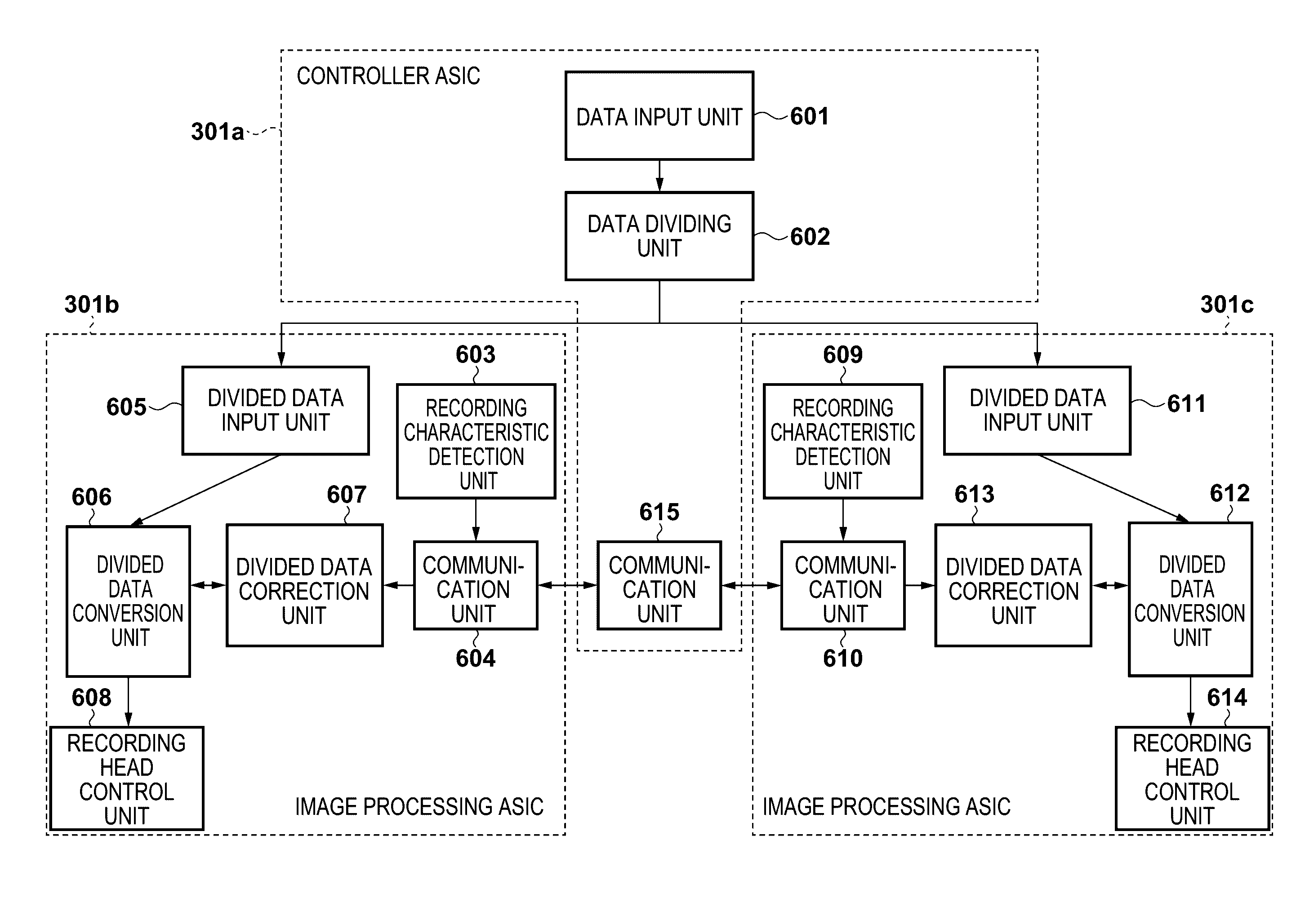
[0089]The second embodiment will be described below. The constituent elements of an apparatus according to this embodiment are the same as those in the first embodiment, and a description of them will be omitted. Differences from the first embodiment reside in processing by divided data conversion units 606 and 612 in ASICs 301b and 301c and processing by divided data correction units 607 and 613.
[0090]According to the first embodiment, if recording image data after quantization (binarization) includes ink discharge dots to be recorded by a discharge failure noise, adjacent non-ink discharge dots are changed to discharge dots. In contrast to this, the second embodiment implements this operation by head shading processing before binarization. Divided data correction units 607 and 612 perform this head shading processing.
[0091]As in the first embodiment, a recording characteristic detection unit 603 of the ASIC 301b detects the amounts of ink from the respective nozzles of the respective
third embodiment
[0109]FIGS. 11A and 11B are views showing an example of monitor control in a parallelization system according to the third embodiment of the present invention. Monitor control described below is one type of correction processing performed by divided data correction units 607 and 613 in the respective ASICs.
[0110]A preferred example of processing will be described in detail below. A recording characteristic detection unit 603 of an ASIC 301b generates dot count information by counting the number of dots to be discharged by using a dot count filter 1108 with respect to four-line (depending on the size of a dither matrix for quantization processing) recording image data after quantization stored in a RAM 212b. That is, the value of data to be driven within the filter matrix is counted every time the matrix is moved by one pixel. This dot count information is transmitted to an ASIC 301c via the communication unit 604.
[0111]A recording characteristic detection unit 609 of the ASIC 301c also
PUM
 Abstract
Description
Claims
Application Information
 - R&D Engineer
- R&D Manager
- IP Professional
- Industry Leading Data Capabilities
- Powerful AI technology
- Patent DNA Extraction
Browse by: Latest US Patents, China's latest patents, Technical Efficacy Thesaurus, Application Domain, Technology Topic.
© 2024 PatSnap. All rights reserved.Legal|Privacy policy|Modern Slavery Act Transparency Statement|Sitemap