Gas separation membrane module with integrated filter

a technology of gas separation membrane and filter, which is applied in the direction of membranes, separation processes, dispersed particle separation, etc., can solve the problems of occupying valuable space, difficult to regenerate the beds, and reducing the process efficiency, so as to reduce the space requirements of the gas separation membrane system and eliminate the need for a carbon bed

Inactive Publication Date: 2016-10-20
GENERON IGS
View PDF9 Cites 3 Cited by
  • Summary
  • Abstract
  • Description
  • Claims
  • Application Information

AI Technical Summary

Benefits of technology

The present technology reduces the size required on an air-separation membranes (ASMs) without requiring any external equipment like filters or other components that are necessary when designing them with these systems. This means fewer parts needed while still maintaining their effectiveness at separating gases from liquids effectively.

Problems solved by technology

Gas mixture separated by means of a porous membrane element is commonly achieved due to its ability to efficiently transmit certain types of molecules without losing their effectiveness when exposed to atmospheric conditions during manufacturing processes. However, there exist various technical problem areas related to achieving efficient filtrations within these elements: 1. Different materials like polyethylene sulfide resins cause damage if left unfilterled overboard. These coatings degrade easily causing contamination. Additionally, the coats produced by the deposits tend to block up passageways leading to reduced performance. To prevent them, filters were proposed, including those based upon activated carboxypolysaccharides.

Method used


Image

  • Gas separation membrane module with integrated filter
  • Gas separation membrane module with integrated filter
  • Gas separation membrane module with integrated filter

Examples


example

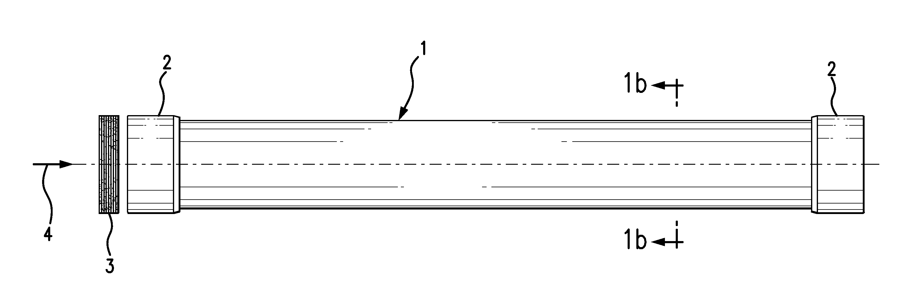
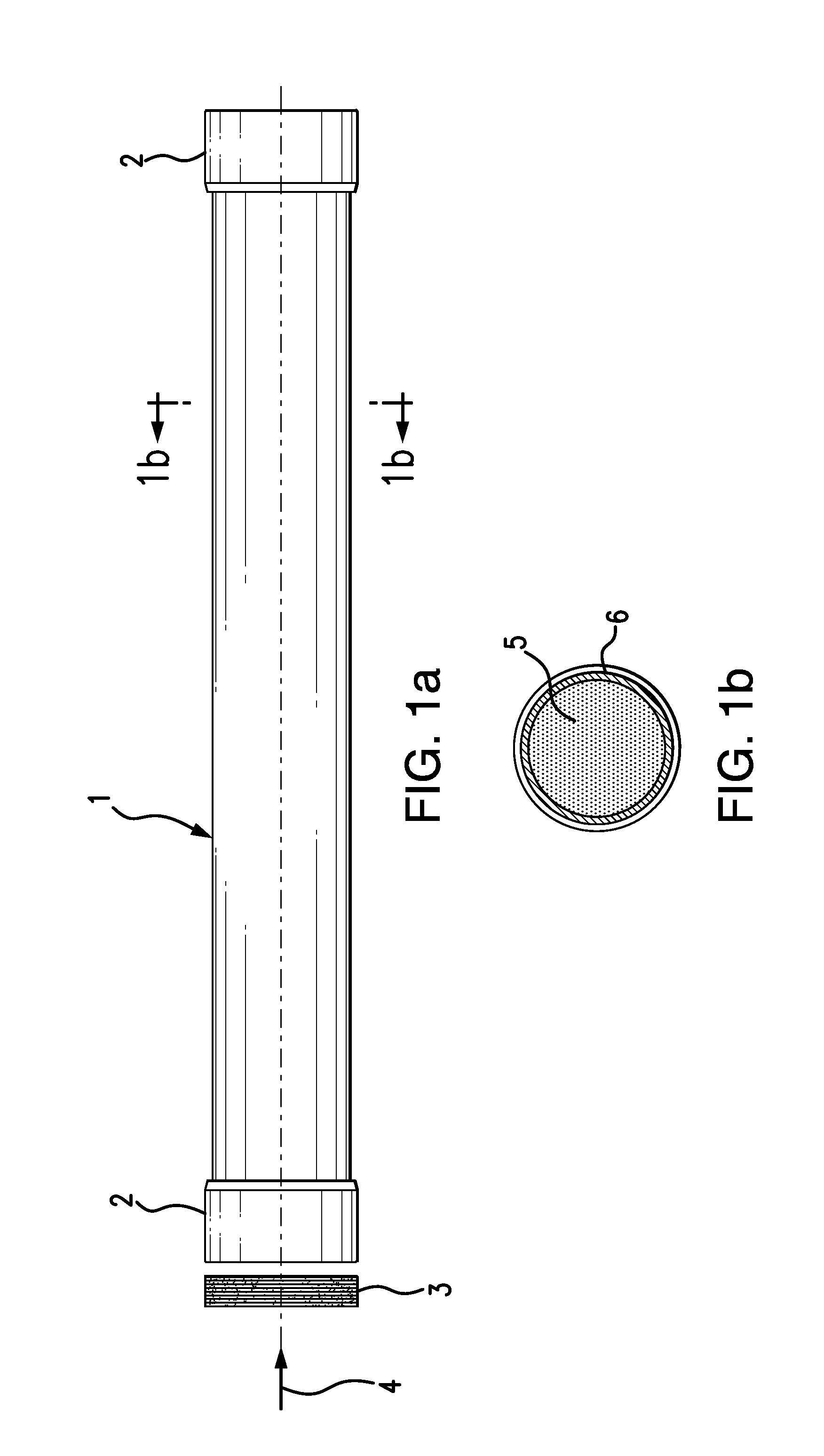
[0054]A commercial air separation module was fitted with a custom pad of Zorflex FM50K, having a six-ply thickness, and having dimensions of 1.125×0.12 inches. The Zorflex material is sold in sheets of 0.5 mm thickness. The pad was attached to the feed end cap of the module.

[0055]The module was operated for three weeks, with a compressed air feed stream having a pressure of 120 psig. The feed stream contained about 0.1-0.5 ppm oil vapor, and the flow rate of the feed stream was 50 scfh, to produce a calculated residence time, in the filter, of 0.045 seconds.

[0056]A second module, without the filter pad, but otherwise the same as the first module, was run with the same feed air stream.

[0057]A third module, similar to the others, was operated with a standard carbon bed, positioned upstream of the module, in which the residence time of the feed stream, in the filter, was one second.

[0058]Both before and after the above-described three-week treatment, the modules were tested at standard co


PUM

PropertyMeasurementUnit
Timeaaaaaaaaaa
Pressureaaaaaaaaaa

Abstract

A gas separation membrane module includes hollow polymeric fibers held within a casing, the fibers being anchored by tubesheets at the ends of the casing. A filter material, preferably made of an activated carbon fiber fabric, is integral with the module, such that all gas entering the module must pass first through the filter before reaching the fibers. The filter may have the form of a circular pad affixed to one of the tubesheets. Alternatively, the filter could be a wrap disposed around the fibers, inside the casing. In another alternative, the filter could be provided within a core tube, in cases where a feed gas is introduced through the core of the module. In another embodiment, the filter could be provided in a separate unit from the gas separation module.

Description


Claims


Application Information

Patent Timeline
Owner GENERON IGS
Why Eureka
Try Eureka