Mobile device
a mobile device and battery technology, applied in the field of mobile devices, can solve the problems of difficult packaging and forming lithium-ion batteries, contributing to the downsizing of battery packs, battery packs, etc., and achieve the effect of reducing the stress on batteries
- Summary
- Abstract
- Description
- Claims
- Application Information
AI Technical Summary
Benefits of technology
Problems solved by technology
Method used
Image

Examples
first embodiment
of the Invention
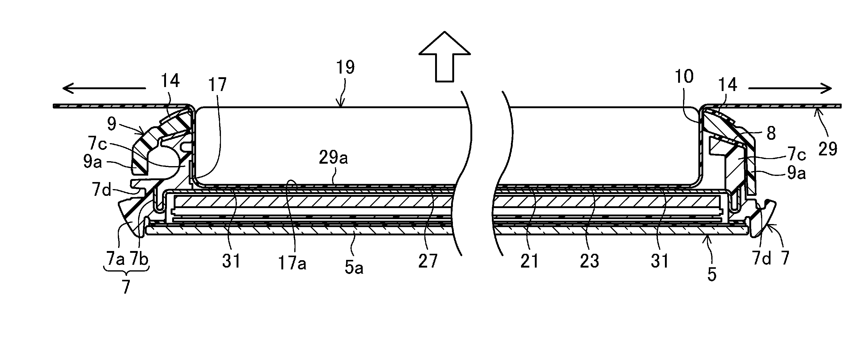
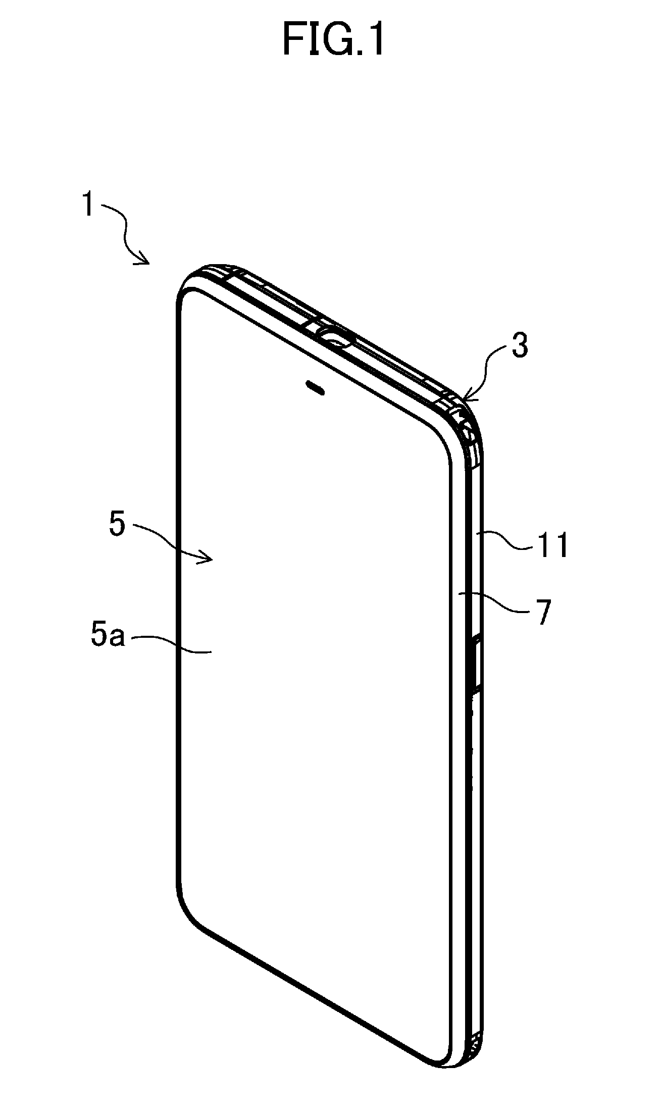
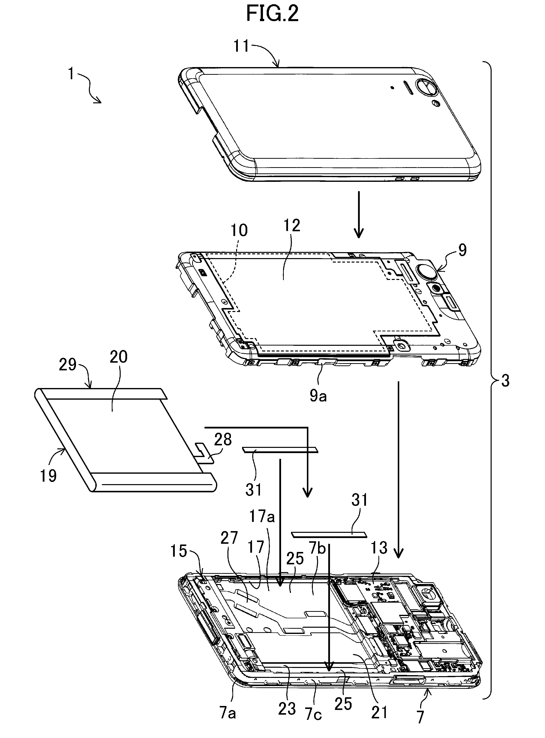
[0026]FIG. 1 is a perspective view illustrating a cellular phone 1, according to this first embodiment, viewed from the front. FIG. 2 is an exploded perspective view of this cellular phone 1. FIG. 3 is a rear view of the cellular phone 1 accommodating a control circuit board 13 of a front cabinet 7. The front cabinet 7 constitutes a casing 3 of the cellular phone 1. Furthermore, FIG. 4 is a cross-sectional view of the cellular phone 1 seen along lines IV-IV in FIG. 3.
[0027]As illustrated in FIGS. 1 and 2, the cellular phone 1 is a mobile device called a “single-piece smartphone”. The cellular phone 1 has the casing 3 shaped into a flat and general rectangle when viewed from the front. The casing 3 includes multiple electronics parts such as a speaker, a microphone, a camera unit, a card connector, a control circuit board 13, and a battery pack 19. The control circuit board 13 controls operations of the speaker, the microphone, the camera unit, and the card connector.
[00
second embodiment
of the Invention
[0054]The cellular phone 1 according to a second embodiment is different from that according to the first embodiment in that a pull-off tab 33 is provided to the battery pack 19. Note that, the embodiments below are the same in the configuration as the first embodiment regarding the cellular phone 1, except a configuration of the low adhesive sheet 29, and the pull-off tab 33 additionally provided. Thus, the same configurations are to be referred to those in the first embodiment with reference to FIGS. 1 to 6, and the details thereof shall be omitted.
[0055]FIG. 7A is a perspective view illustrating the battery pack 19 provided with the pull-off tab 33 according to the second embodiment. FIG. 7B is a perspective view illustrating how to attach the pull-off tab 33 to the battery pack 19 together with the low adhesive sheet 29. As illustrated in FIG. 7A, the pull-off tab 33 is provided between the battery pack 19 and the low adhesive sheet 29 in the second embodiment. The
third embodiment
of the Invention
[0060]The cellular phone 1 according to a third embodiment is different in the configuration of the low adhesive sheet 29 attached to the battery pack 19 from the cellular phone 1 according to the first embodiment. FIG. 9A is a plan view of the low adhesive sheet 29 according to this third embodiment. FIG. 9B is a perspective view illustrating the battery pack 19 with the low adhesive sheet 29 attached thereto. FIG. 9C is a perspective view illustrating how the low adhesive sheet 29 is attached to the battery pack 19.
[0061]The low adhesive sheet 29 in this third embodiment has multiple through holes 35 and 37. Specifically, a portion of the low adhesive sheet 29, to be attached to the front face of the battery pack 19, has multiple first through holes 35 (five first through holes in an example in FIG. 9A) spaced apart from each other. These first through holes 35 are formed to let air, trapped between the adhesive face 29a of the low adhesive sheet 29 and the battery pa
PUM
 Abstract
Description
Claims
Application Information
 - R&D Engineer
- R&D Manager
- IP Professional
- Industry Leading Data Capabilities
- Powerful AI technology
- Patent DNA Extraction
Browse by: Latest US Patents, China's latest patents, Technical Efficacy Thesaurus, Application Domain, Technology Topic.
© 2024 PatSnap. All rights reserved.Legal|Privacy policy|Modern Slavery Act Transparency Statement|Sitemap