System for flushing pipe plumbing using microbubbles, method therefor, and ship or maritime plant having same

a technology of microbubbles and flushing pipes, which is applied in the direction of separation processes, vessel construction, filtration separation, etc., can solve the problems of pipe damage, scale removal cost increase, and pipe cannot perform the function as designed, so as to increase the flow rate, increase the reynolds number, and increase the removal efficiency of foreign substances

Inactive Publication Date: 2018-03-22
SAM YOUNG TECH +1
View PDF0 Cites 0 Cited by
  • Summary
  • Abstract
  • Description
  • Claims
  • Application Information

AI Technical Summary

Benefits of technology

The inventors have developed an improved way to clean pipes that uses tiny bubbles instead of regular filters or chemical agents like chlorine gas. This helps improve its effectiveness while reducing costs associated therewith. Additionally, they use this technology to detect any impurities remaining inside their pipeline without having them removed during maintenance work hours. Overall, these technical improvements make it easier and more efficient to maintain the quality of crude oils used throughout industry's production processes.

Problems solved by technology

The technical problem addressed in this patented method relates to removing scale deposits inside pipes caused by corrosion without causing damage when replacing them afterwards.

Method used


Image

  • System for flushing pipe plumbing using microbubbles, method therefor, and ship or maritime plant having same
  • System for flushing pipe plumbing using microbubbles, method therefor, and ship or maritime plant having same
  • System for flushing pipe plumbing using microbubbles, method therefor, and ship or maritime plant having same

Examples


Embodiment Construction

[0043]Hereinafter, the present invention will now be described in detail with reference to the attached drawing.

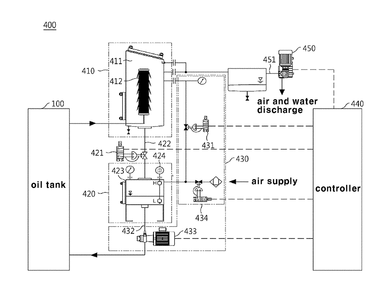
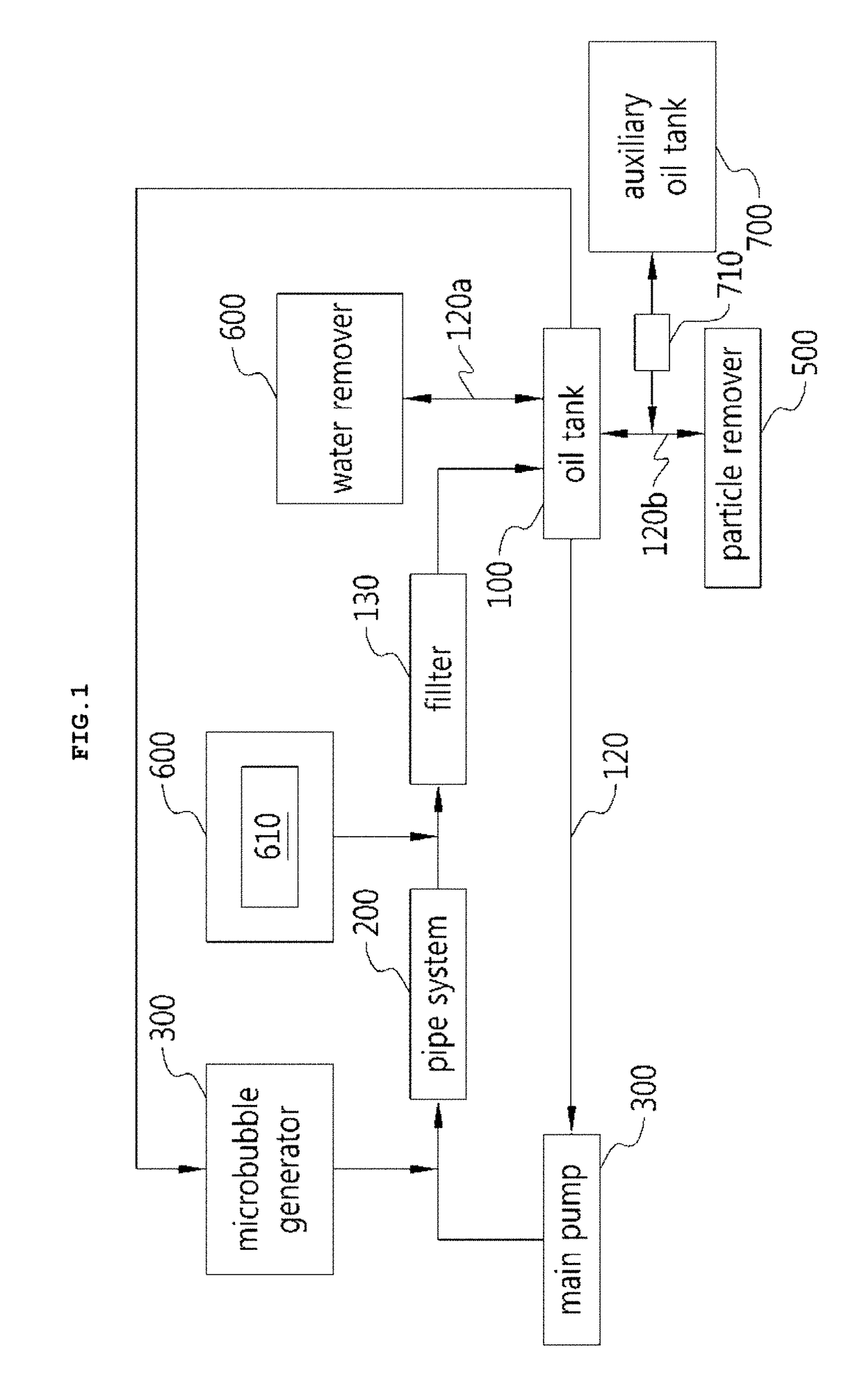
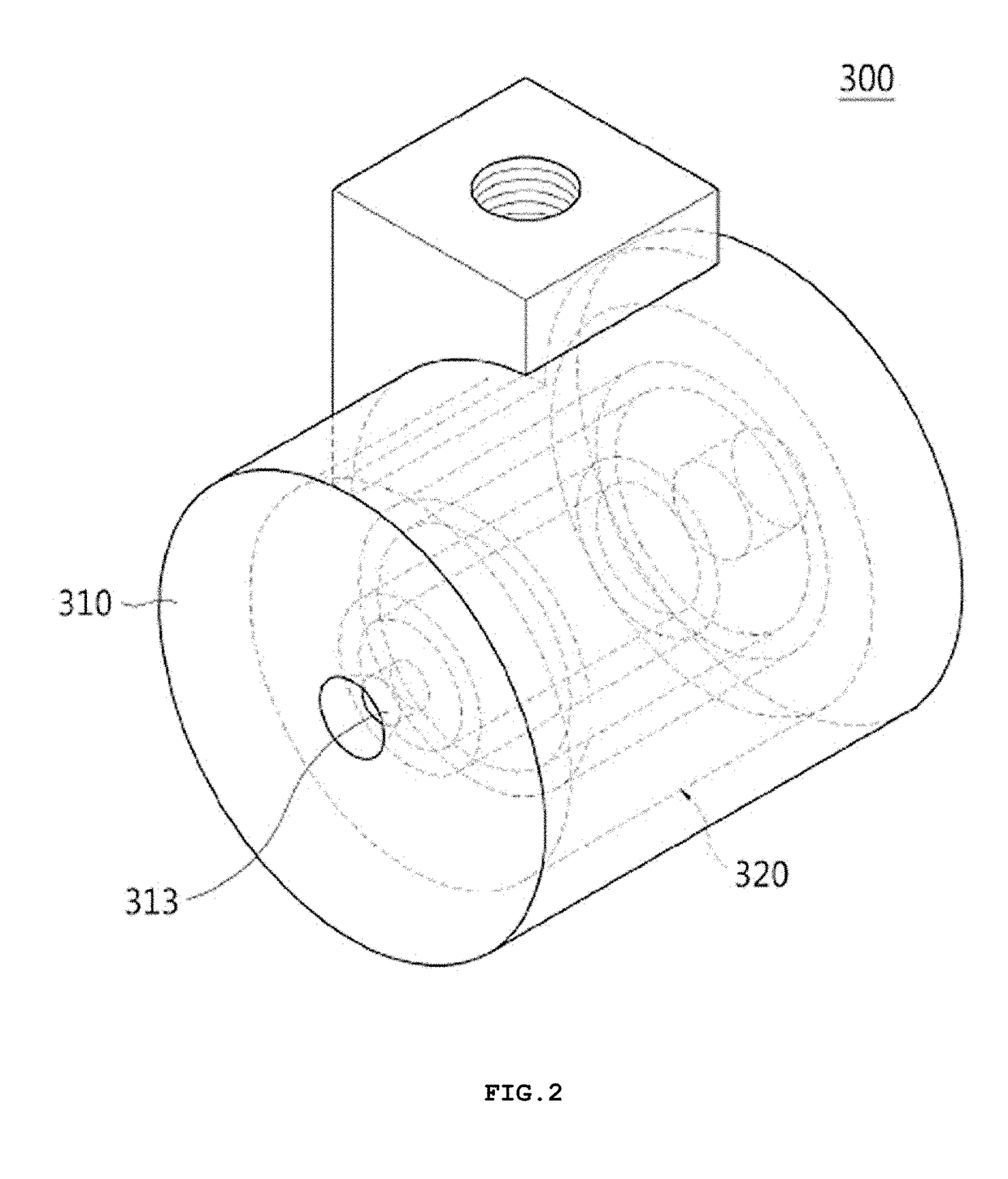
[0044]FIG. 1 is a block diagram showing a system for flushing a pipe using microbubbles according to the present invention, FIG. 2 is a perspective view showing the interior of a microbubble generator in the system according to the present invention, FIG. 3 is a sectional view showing the microbubble generator of FIG. 2, FIG. 4 is a block diagram showing a water remover in the system according to the present invention, FIG. 5 is a block diagram showing the internal structure of a particle remover in the system according to the present invention, and FIG. 6 is a sectional view showing the electrodes of the particle remover of FIG. 5.

[0045]FIG. 7 is a flowchart showing a method for flushing a pipe using microbubbles according to the present invention, FIG. 8 is a flowchart showing the step of generating the microbubbles in the method according to the present invention, and FIG.


PUM

PropertyMeasurementUnit
Flow rateaaaaaaaaaa
Adsorption entropyaaaaaaaaaa
Electric forceaaaaaaaaaa

Abstract

A flushing system comprises: an oil tank for storing oil; a pipe system connected to the oil tank by means of a pipe to circulate the oil by means of the operation of a main pump; a microbubble generator connected to at least any one of the oil tank and the pipe system to generate the microbubbles in the pipe along which the oil flows and in the oil tank and thus to inject the microbubbles into the pipe; a water remover connected to the oil tank to remove the microbubbles and water from the oil; and a particle remover connected to the oil tank to remove microbubbles and foreign substances from the oil by means of electric precipitation.

Description


Claims


Application Information

Patent Timeline
Owner SAM YOUNG TECH
Why Eureka
Try Eureka