Stable inp quantum dots with thick shell coating and method of producing the same
a quantum dots and thick shell technology, applied in the field of high-luminescent quantum dots, can solve the problems of cadmium, mercury, or lead posing serious threats to human health and the environment, prone to degradation mechanisms, and most quantum dots do not retain their original high quantum yield
- Summary
- Abstract
- Description
- Claims
- Application Information
AI Technical Summary
Benefits of technology
Problems solved by technology
Method used
Image


Examples
example 1
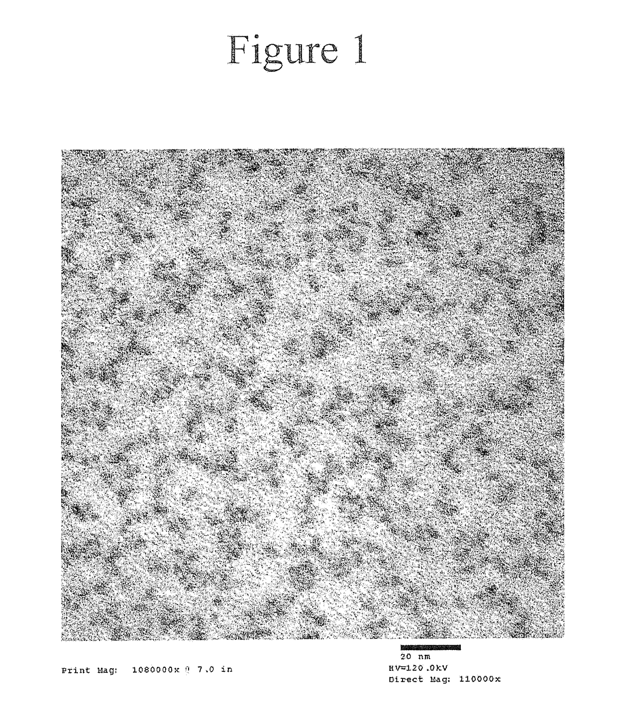
[0286]The deposition of a thick ZnSe / ZnS multi-layered shell on a green InP core using zinc oleate, tri-n-butylphosphine selenide, and octanethiol as precursors at temperatures exceeding 280° C. is described. Synthesis of a green InP core is disclosed in U.S. Patent Appl. Publication No. 2014 / 0001405.
[0287]The stoichiometry was calculated for InP cores with an absorption peak at 470 nm, a concentration in hexane of 66.32 mg / mL, and a shell thickness of 3.5 monolayers of ZnSe and 4.5 monolayers of ZnS. Zinc oleate was prepared from zinc acetate and oleic acid as a solid. TBPSe was prepared from selenium pellets and tri(n-butyl)phosphine.
[0288]To a 250 mL 3 neck round-bottom flask was added 3.48 g (5.54 mmol, 13.38 equivalents) of zinc oleate and 33.54 mL of 1-octadecene at room temperature in air. The flask was equipped with a stir bar, a rubber septum, a Schlenk adaptor, and a thermocouple. The flask was connected to a Schlenk line via a rubber hose. Inert conditions were establi
example 2
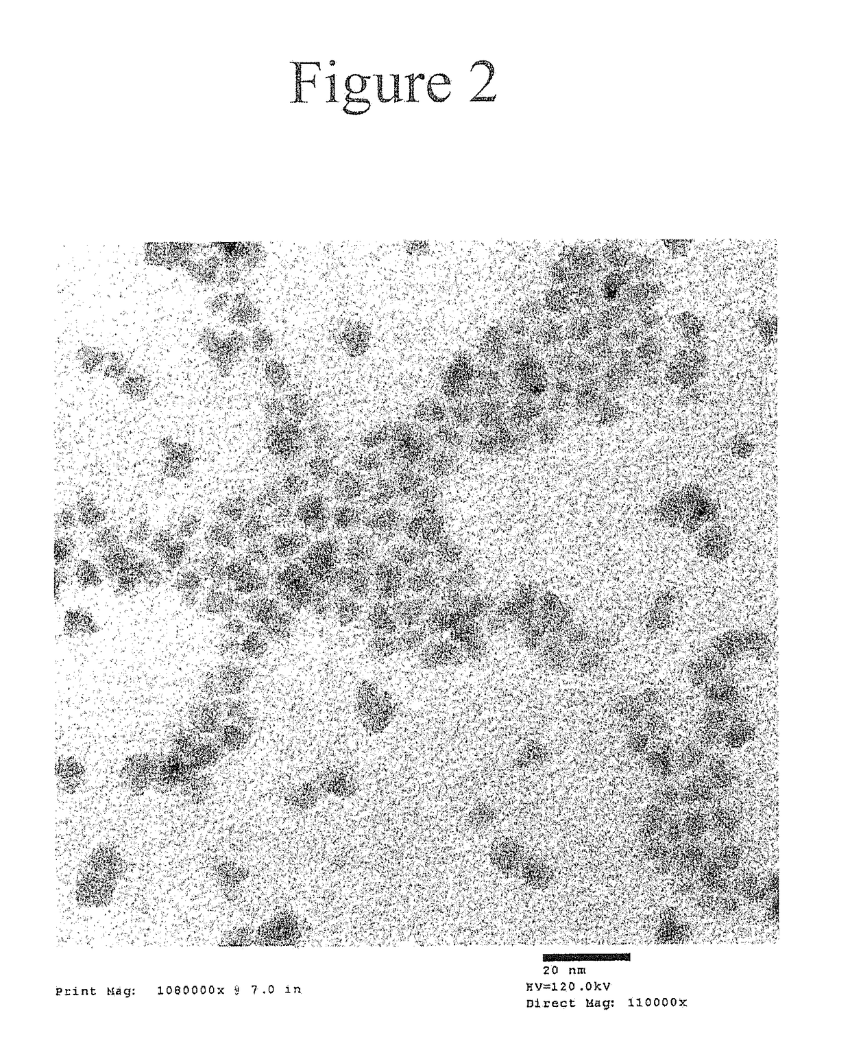
[0295]The deposition of a thick ZnSe / ZnS multi-layered shell on a green InP core using zinc oleate, tri-n-butylphosphine selenide, and octanethiol as precursors at temperatures exceeding 280° C. is described. The resultant nanostructure had a target shell thickness of 1.5 monolayers of ZnSe and 2.5 monolayers of ZnS.
[0296]To a 100 mL 4 neck round-bottom flask was added 0.409 g (0.651 mmol, 3.1 equivalents) of zinc oleate and 2 mL of 1-octadecene at room temperature in air. The flask was equipped with a glass stopper, a rubber septum, a Schlenk adaptor, and a thermocouple. The flask was connected to a Schlenk line via a rubber hose. Inert conditions were established by at least three cycles of vacuum (<50 mtorr) and nitrogen flushing. The mixture was heated to 80° C. under nitrogen flow to afford a clear solution. The temperature was maintained and the flask was put under vacuum once again and pumped until no further gas evolution (<50 mtorr) was observed. The heating mantle was remov
example 3
[0303]Nanostructures with green InP cores with a target shell thickness of 1.5 monolayers of ZnSe and (A) 4.5 monolayers of ZnS; and (B) 7.5 monolayers of ZnS were prepared using the synthetic method of Example 2 and varying the amount of zinc oleate and octanethiol added to the reaction mixture. The following amounts of zinc oleate and octanethiol precursors were used to prepare the ZnS shell:
(A) for the 4.5 monolayers of ZnS:
[0304]4.47 g of zinc oleate; and
[0305]1.13 mL of octanethiol.
(B) for the 7.5 monolayers of ZnS:
[0306]11.44 g of zinc oleate; and
[0307]2.88 mL of octanethiol.
PUM
| Property | Measurement | Unit |
|---|---|---|
| Fraction | aaaaa | aaaaa |
| Fraction | aaaaa | aaaaa |
| Thickness | aaaaa | aaaaa |
Abstract
Description
Claims
Application Information
 - R&D Engineer
- R&D Manager
- IP Professional
- Industry Leading Data Capabilities
- Powerful AI technology
- Patent DNA Extraction
Browse by: Latest US Patents, China's latest patents, Technical Efficacy Thesaurus, Application Domain, Technology Topic.
© 2024 PatSnap. All rights reserved.Legal|Privacy policy|Modern Slavery Act Transparency Statement|Sitemap