Cutting apparatus and rotary blade

a cutting apparatus and rotary blade technology, applied in cell components, electrochemical generators, transportation and packaging, etc., can solve the problems of defective cutting, foreign objects such as cuttings not easily adhered to the smooth surface portion, and the friction against the rotary blade may increase, so as to and prolong the life of the rotary blad

Active Publication Date: 2018-10-04
TOYOTA JIDOSHA KK
View PDF13 Cites 1 Cited by
  • Summary
  • Abstract
  • Description
  • Claims
  • Application Information

AI Technical Summary

Benefits of technology

This patent describes a method for improving the lifespan of a device called a splitter by providing a space between the rotating blades of the machine. By doing this, there are fewer parts needed to break down the materials being processed, resulting in longer devices lasting more reliable. Additionally, the use of thinner metallic foils makes them easier to flow through during manufacturing processes. Overall, these technical improvements improve the performance and durability of the splitter.

Problems solved by technology

The technical problem addressed in this patent is how to improve the durability of cutting tools used during production of lithium batteries by providing a more effective way to cut them without requiring lubrication or other materials that may reduce their effectiveness.

Method used


Image

  • Cutting apparatus and rotary blade
  • Cutting apparatus and rotary blade
  • Cutting apparatus and rotary blade

Examples


Embodiment Construction

[0019]Hereinbelow, embodiments of a cutting apparatus proposed herein will be described. It should be noted that the embodiments described herein are, of course, not intended to limit the present invention. The present invention is not limited to the embodiments described herein unless specifically stated otherwise.

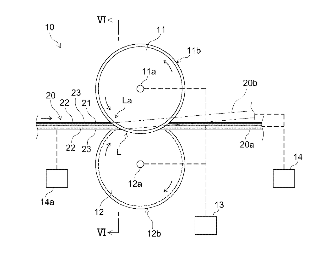
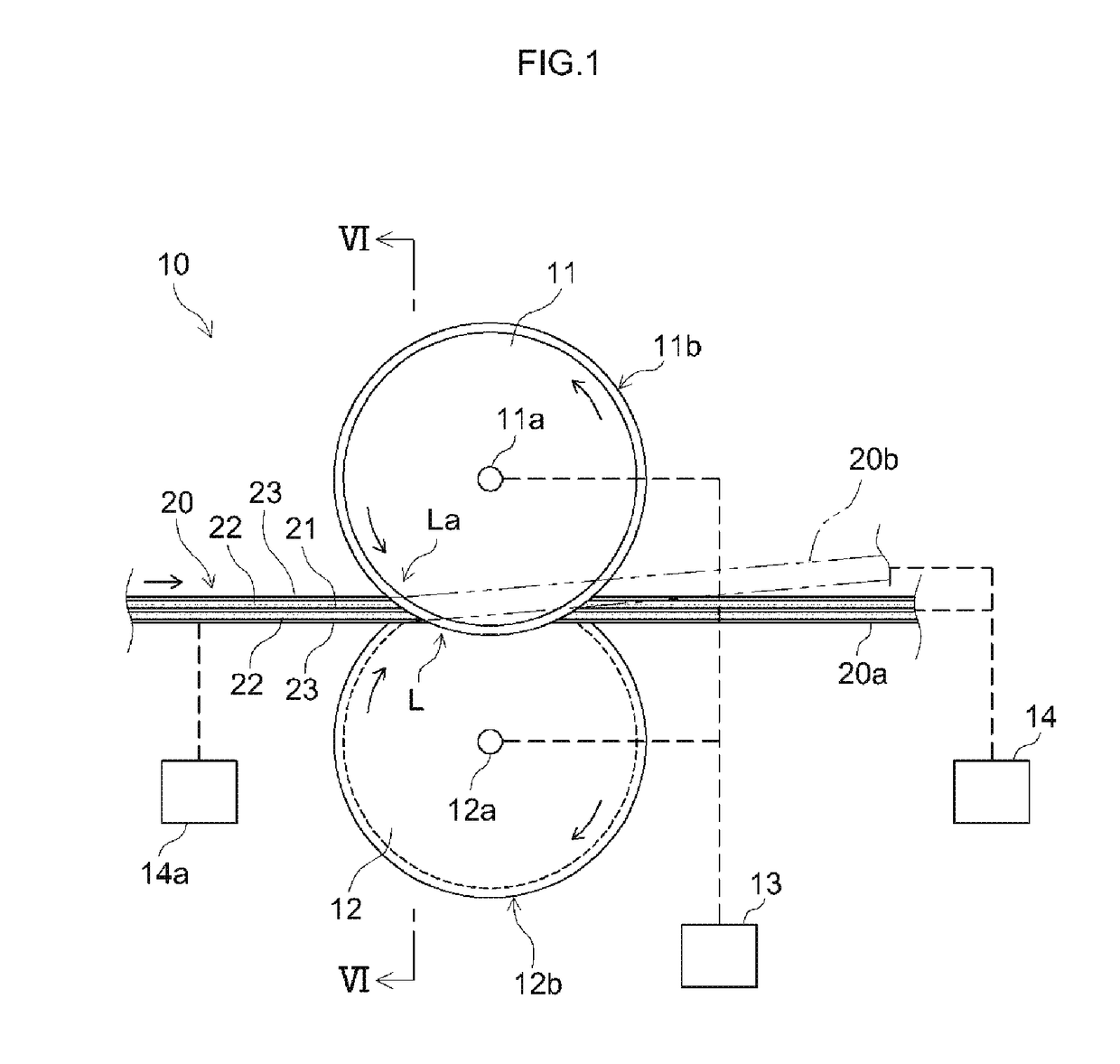
[0020]FIG. 1 is a side view illustrating a cutting apparatus 10 proposed herein. FIG. 2 is a front view illustrating an arrangement of a first rotary blade 11 and a second rotary blade 12 of the cutting apparatus 10. FIG. 3 is a partially enlarged cross-sectional view illustrating a circumferential edge portion 11b (blade edge) of the first rotary blade 11. FIG. 4 is a plan view of an electrode sheet 20 that is to be cut. FIG. 5 is a cross-sectional view of the electrode sheet 20 that is to be cut.

[0021]The electrode sheet 20 to be cut herein is what is called a separator-integrated-type electrode sheet, as illustrated in FIGS. 4 and 5. The electrode sheet 20 includes a curr


PUM

PropertyMeasurementUnit
Lengthaaaaaaaaaa
Widthaaaaaaaaaa
Speedaaaaaaaaaa

Abstract

Each of a first rotary blade and a second rotary blade includes a rough surface portion and a smooth surface portion. The rough surface portion has a predetermined width from a blade edge at its circumferential edge portion and has an arithmetical mean roughness of greater than 0.5. The smooth surface portion is provided radially inward of the rough surface portion and has an arithmetical mean roughness less than the arithmetical mean roughness of the rough surface portion.

Description


Claims


Application Information

Patent Timeline
Owner TOYOTA JIDOSHA KK
Why Eureka
Try Eureka