Random code generator
- Summary
- Abstract
- Description
- Claims
- Application Information
AI Technical Summary
Benefits of technology
Problems solved by technology
Method used
Image

Examples
first embodiment
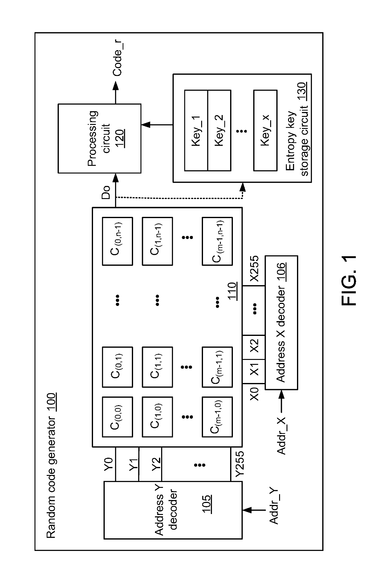
[0018]FIG. 1 is a schematic block diagram illustrating the architecture of a random code generator according to the present invention. The random code generator 100 comprises a PUF entropy pool 110, an address Y decoder 105, an address X decoder 106, an entropy key storage circuit 130 and a processing circuit 120. The PUF entropy pool 110 is a PUF cell comprising m×n PUF cells C(0,0)˜C(m-1,n-1). The PUF entropy pool 110 has a density of K entropies, wherein K=m×n. The entropy key storage circuit 130 has many implementation examples. For example, the entropy key storage circuit 130 comprises plural registers. In some other embodiments, the entropy key storage circuit 130 is integrated into the processing circuit 120.
[0019]For example, the PUF entropy pool 110 comprises 256×256 PUF cells. That is, m=n=256. The address Y decoder 105 comprises 256 Y control lines Y0˜Y255, which are connected with the PUF entropy pool 110. The address Y decoder 105 activates one of the 256 Y control lines Y
second embodiment
[0073]FIG. 6 is a schematic block diagram illustrating the architecture of a random code generator according to the present invention. The random code generator 600 comprises a PUF entropy pool 110, an address Y decoder 605, an address X decoder 606, an entropy key storage circuit 630 and a processing circuit 120. In comparison with the random code generator 100, the address Y decoder 605, the address X decoder 606 and the entropy key storage circuit 630 of the random code generator 600 are distinguished. For succinctness, only the relationships between the address Y decoder 605, the address X decoder 606 and the entropy key storage circuit 630 will be described as follows.
[0074]In this embodiment, the entropy key storage circuit 630 provides plural entropy keys to the processing circuit 120. Moreover, the entropy key storage circuit 630 further provides entropy keys to the address Y decoder 605 and the address X decoder 606. For example, the entropy key storage circuit 630 provides th
third embodiment
[0079]FIG. 7 is a schematic block diagram illustrating the architecture of a random code generator according to the present invention. The random code generator 700 comprises a PUF entropy pool 110, an address Y decoder 705, an address X decoder 706, an entropy key storage circuit 130 and a processing circuit 120. In comparison with the random code generator 100, the address Y decoder 705 and the address X decoder 706 of the random code generator 700 are distinguished. For succinctness, only the relationship between the address Y decoder 705 and the address X decoder 706 will be described as follows.
[0080]In this embodiment, the address Y decoder 705 receives the address Y signal Addr_Y and a first challenging signal Dc1, and the address X decoder 706 receives the address X signal Addr_X and a second challenging signal Dc2. The first challenging signal Dc1 and the second challenging signal Dc2 are provided by an external device outside the random code generator 700.
[0081]Firstly, the a
PUM
 Abstract
Description
Claims
Application Information
 - R&D Engineer
- R&D Manager
- IP Professional
- Industry Leading Data Capabilities
- Powerful AI technology
- Patent DNA Extraction
Browse by: Latest US Patents, China's latest patents, Technical Efficacy Thesaurus, Application Domain, Technology Topic.
© 2024 PatSnap. All rights reserved.Legal|Privacy policy|Modern Slavery Act Transparency Statement|Sitemap