Brake pad, disk brake assembly, and vehicle

a technology for brake pads and disc brakes, applied in the field of brake pads, to achieve the effect of increasing the size of the boundary layer and therefore the adhesion between the friction pad and the mounting structure, increasing mechanical strength, and being more robus

Inactive Publication Date: 2020-01-16
MAT COMML VEHICLE PROD GMBH
View PDF0 Cites 0 Cited by
  • Summary
  • Abstract
  • Description
  • Claims
  • Application Information

AI Technical Summary

Benefits of technology

In this patent, there are two ways to improve the bonding between a friction pad and a mounting structure: 1. Mixing the frictional material and resin together to create an adhesive layer on both components. By doing this, it becomes easier to achieve strong bonds without adding extra steps or complicating processes. 2. Using large particles of the friction material instead of small ones, which helps to make the boundary layers between them smoother. These boundaries also enhance the overall bonding process.

Problems solved by technology

This patent describes how braking can be done effectively without causing damage to the wheel when it's stopped too quickly. It explains that there are two types of braking: one uses frictional force between the brake disc and the brake caliper, while another uses an elastomeric layer attached to the brake caliper. These technical features help prevent damage from happening during braking.

Method used


Image

  • Brake pad, disk brake assembly, and vehicle
  • Brake pad, disk brake assembly, and vehicle
  • Brake pad, disk brake assembly, and vehicle

Examples


Embodiment Construction

[0052]Like numbered elements in these figures are either equivalent elements or perform the same function. Elements which have been discussed previously will not necessarily be discussed in later figures if the function is equivalent.

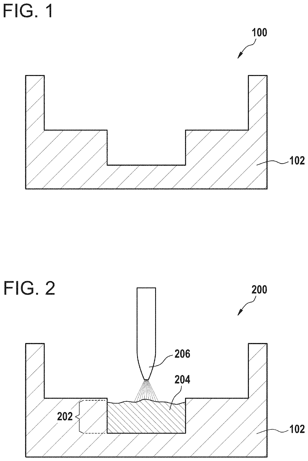
[0053]FIGS. 1-5 illustrate the manufacture of a brake pad using a single press curing step. First in FIG. 1 the step of providing 100 a cure mold 102 is shown. Next in FIG. 2 the step of filling a first portion 202 of the cure mold 102 with particulate friction material 204 is shown. The particulate friction material 204 may for example be provided in either a powder or liquid form depending upon the type or form of the resin used. In this example there is a nozzle 206 which is spraying the particulate friction material 204 into the first portion 202 of the cure mold 100.

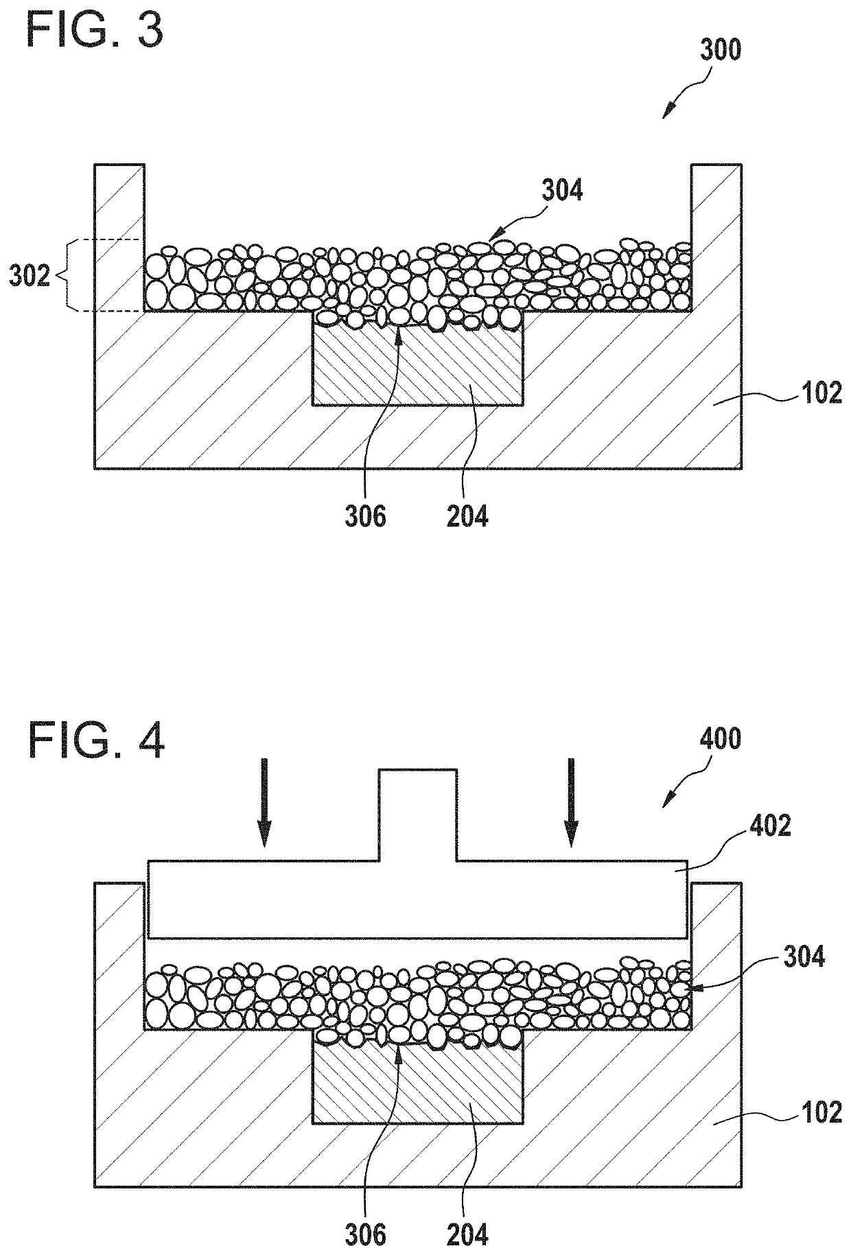
[0054]FIG. 3 shows the filling 300 of a second portion 302 of the cure mold 102 with a granulated thermoset plastic 304. After the particulate friction material 204 was filled into the cur


PUM

PropertyMeasurementUnit
Adhesion strengthaaaaaaaaaa
Frictionaaaaaaaaaa

Abstract

A method of manufacturing a brake pad including a friction pad and a mounting structure includes providing a cure mold; filling the cure mold with granulated thermoset plastic to form the mounting structure and particulate friction material to form the friction pad; and press curing in a single step the filled cure mold to form the brake pad.

Description


Claims


Application Information

Patent Timeline
Owner MAT COMML VEHICLE PROD GMBH
Why Eureka
Try Eureka