Tool mounting for a hand machine tool

a technology for power tools and tools, which is applied in the field of tool mounts for hand power tools, can solve the problems of high impact energy, special technical measures, and wear of the tool mounts, and achieve the effect of high degree of true running of the tool in the tool moun

Inactive Publication Date: 2005-02-15
ROBERT BOSCH GMBH
View PDF16 Cites 20 Cited by
  • Summary
  • Abstract
  • Description
  • Claims
  • Application Information

AI Technical Summary

Benefits of technology

This patented technology helps prevent damage caused by tools that run too much during their lifespan. It uses a special case made from plastic or rubber material for the tool's sheath. By adding this case, it becomes more durable over time.

Problems solved by technology

This patent describes a problem with tools used for electric power tools like hedge trimmers. These tools have a rotating and impacting drive that requires frequent maintenance due to wearing out over time. Existing solutions involve expensive and complex manufacturing processes, making them difficult to use economically.

Method used


Image

  • Tool mounting for a hand machine tool
  • Tool mounting for a hand machine tool

Examples


Embodiment Construction

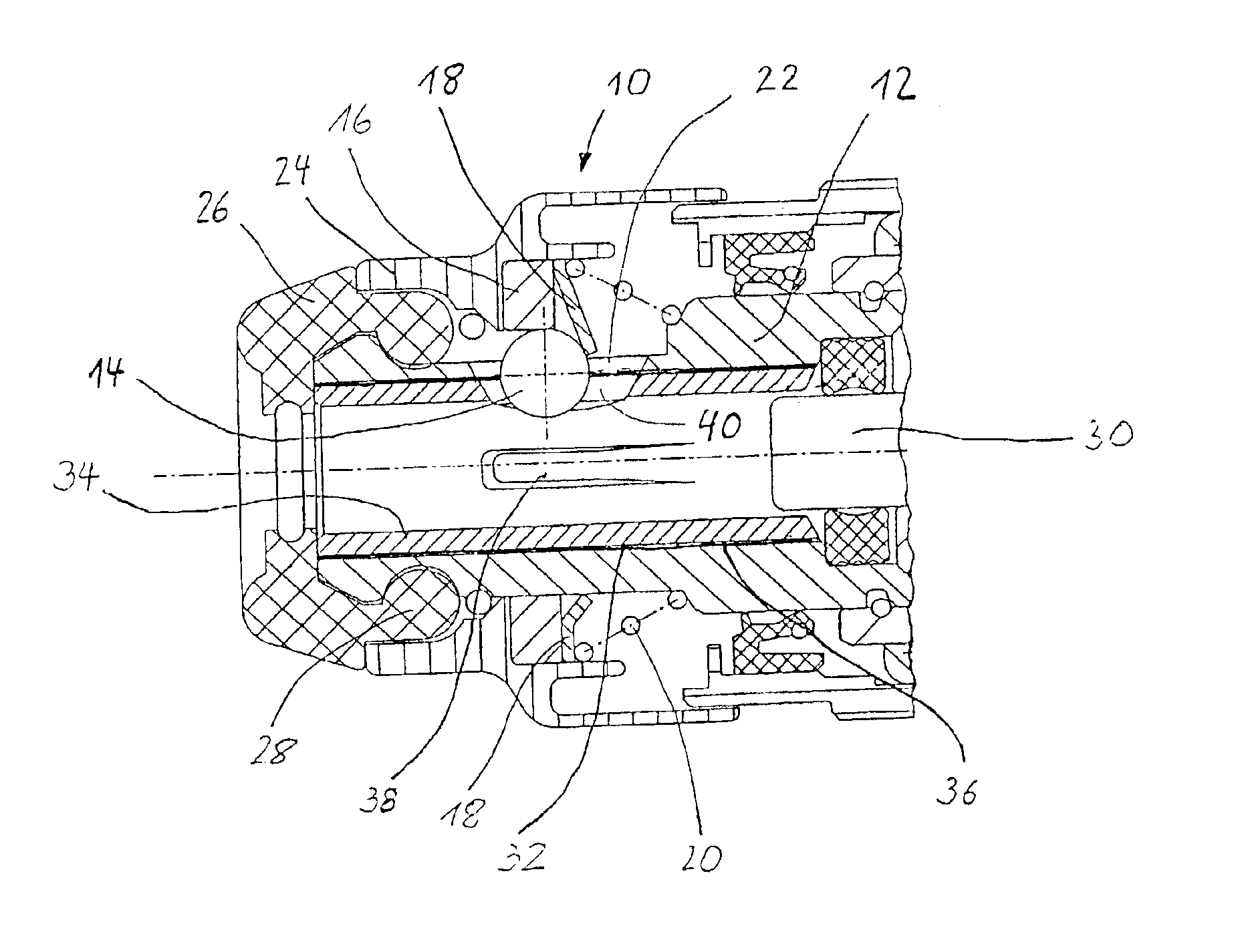
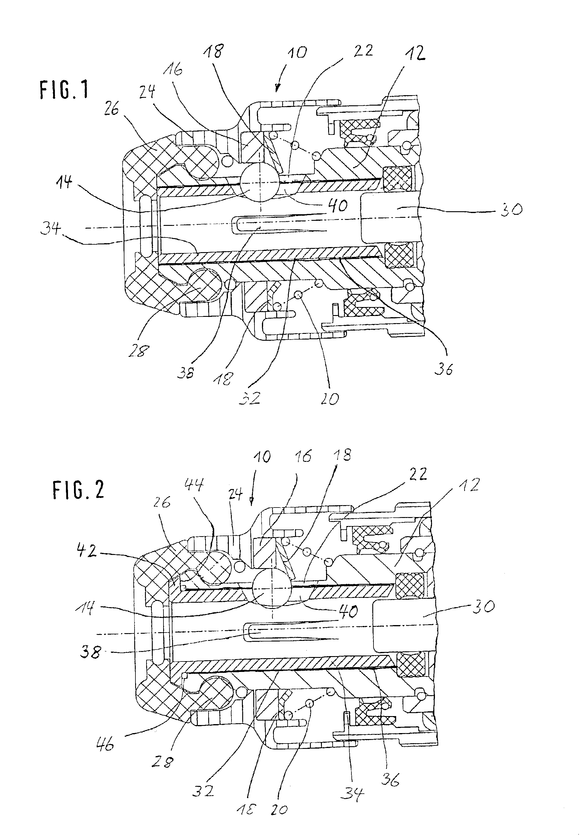
FIG. 1 shows sections of a cross section through a tool mount 10 that is located on a rotating and / or impacting hand power tool. This tool mount 10 is used to mount tools with grooves. The tool mount 10 has a body 12 in which a radially displaceable clamping body—a clamping ball 14 in the exemplary embodiment—is supported. This clamping ball 14 is capable of being guided into a groove located on the shank end of the tool (not shown in the drawing), and it is held in its clamped position by a retaining sleeve 16 that can be moved axially within limits, and by a holding sleeve 16. The retaining sleeve 16 is loaded in the direction of its retaining position by a compression spring 20 via the holding sleeve 18. The compression spring 20 is supported, at the machine end, on the body 12. The retaining sleeve 16 is also supported on the body 12.

When the clamping ball 14 is in the clamped position, the retaining sleeve 16 covers the clamping ball 14 radially, and the holding sleeve 18 secure


PUM

PropertyMeasurementUnit
Electrical resistanceaaaaaaaaaa

Abstract

The tool mount has a body (12) with means for housing a tool with grooves, whereby the body (12) is equipped with a damping mechanism (14, 16, 18, 20) with which the tool can be clamped in position in the body (12), and an operating element (24) for unclamping the tool is provided.
A wear-resistant tool mount requiring low production expenses has a housing sleeve (34) for the tool. The housing sleeve is inserted in the body (12) and is made of a harder material than the body (12).

Description


Claims


Application Information

Patent Timeline
Owner ROBERT BOSCH GMBH
Why Eureka
Try Eureka